Modelling of Fault
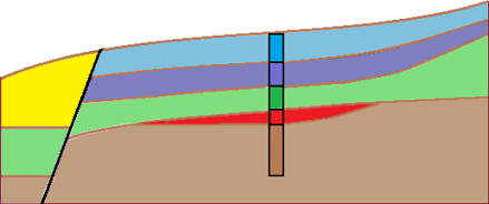
The aim of this example is to model a geological fault, which crosses the construction site. On the left side of the construction site, the subsoil is created by the yellow soil with a thickness of [3 m], other layers are below this layer have a thickness [1 m].
First we enter a fault interface to the master borehole using "Insert (before 1)" button. We enter a depth of lower interface location as [-10 m] - it is located high above the terrain. The fault is made up of new soil "Black".
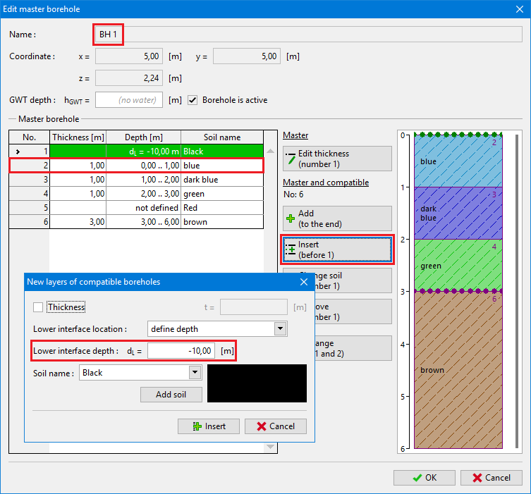 Input of new soil / fault in master borehole
After generating, the model remains same, but we can see a new layer (fault) in the bottom right corner. For better clarity we used a black color.
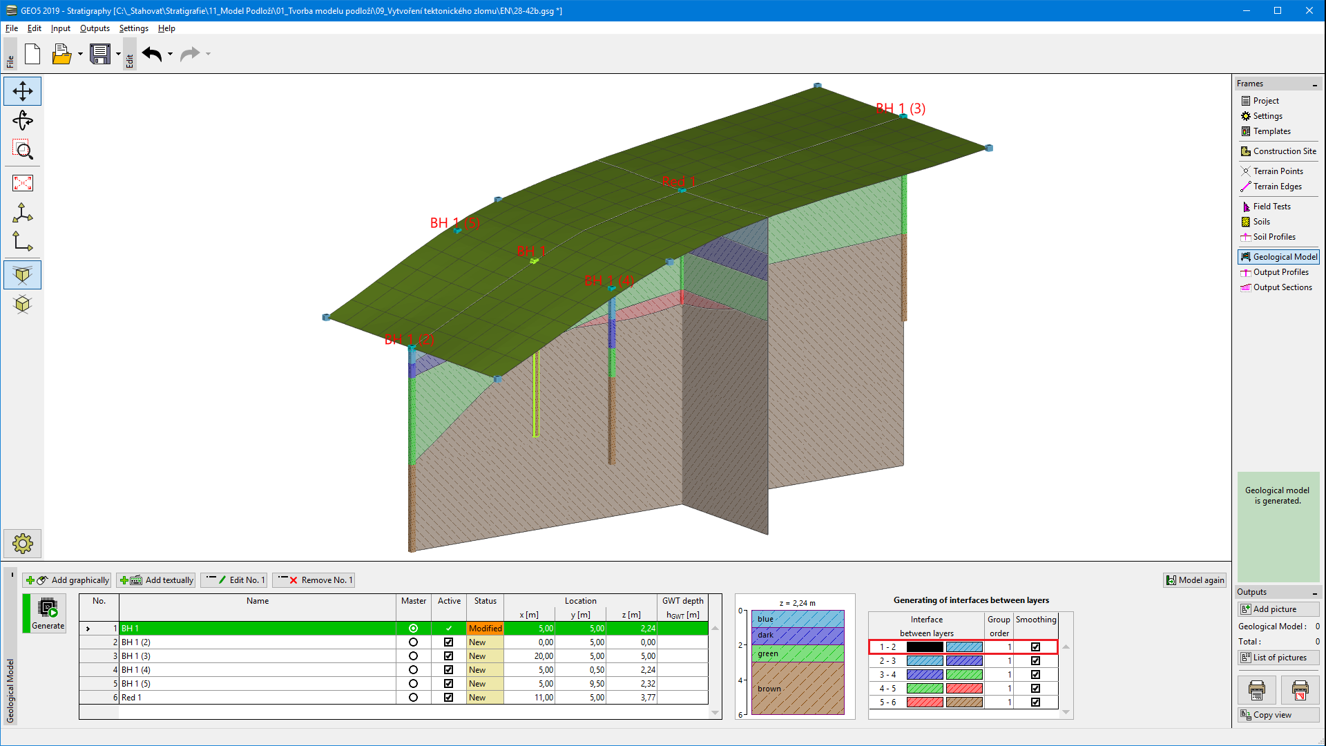 Model with new black layer what represents a fault
In following steps we define a location of fault on the terrain. We define boreholes ZZ 1 [3; 0], ZZ 2 [3,7; 5] and ZZ 3 [4; 10] step by step.
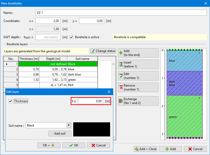
When inputting a borehole textually, an empty dialog window is shown at first. After coordinates input [3; 0], the gelogical profile is loaded from the model. Now we change properties of upper black layer (fault) and enter its thickness as a [0 m].
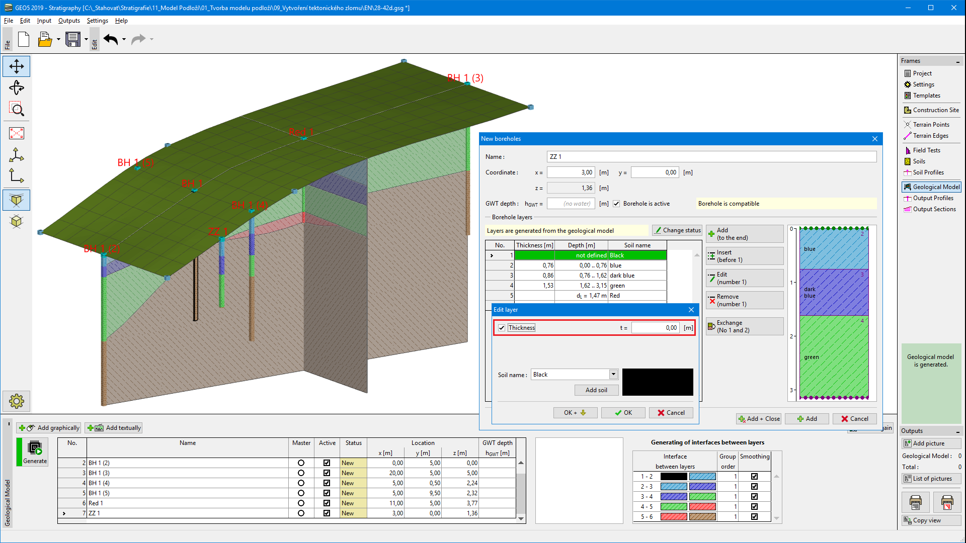 Input of borehole ZZ 1 determining the location of fault on the terrain
 Input of borehole ZZ 1 determining the location of fault on the terrain
We leave using "Add + close" and regenerate the model.
We repeate a process also for boreholes ZZ 2 and ZZ 3 (set a black layer as a [0 m] thickness).
The model must be regenerated after each borehole input. It is necessary for correspondation of borehole to original geological model.
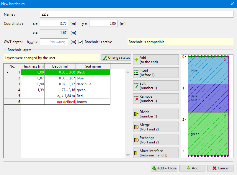 Input of borehole ZZ 2 determining the location of fault on the terrain
After input of the fault on the terrain, we remove boreholes in front of the fault - in this case borehole BH 1(2).
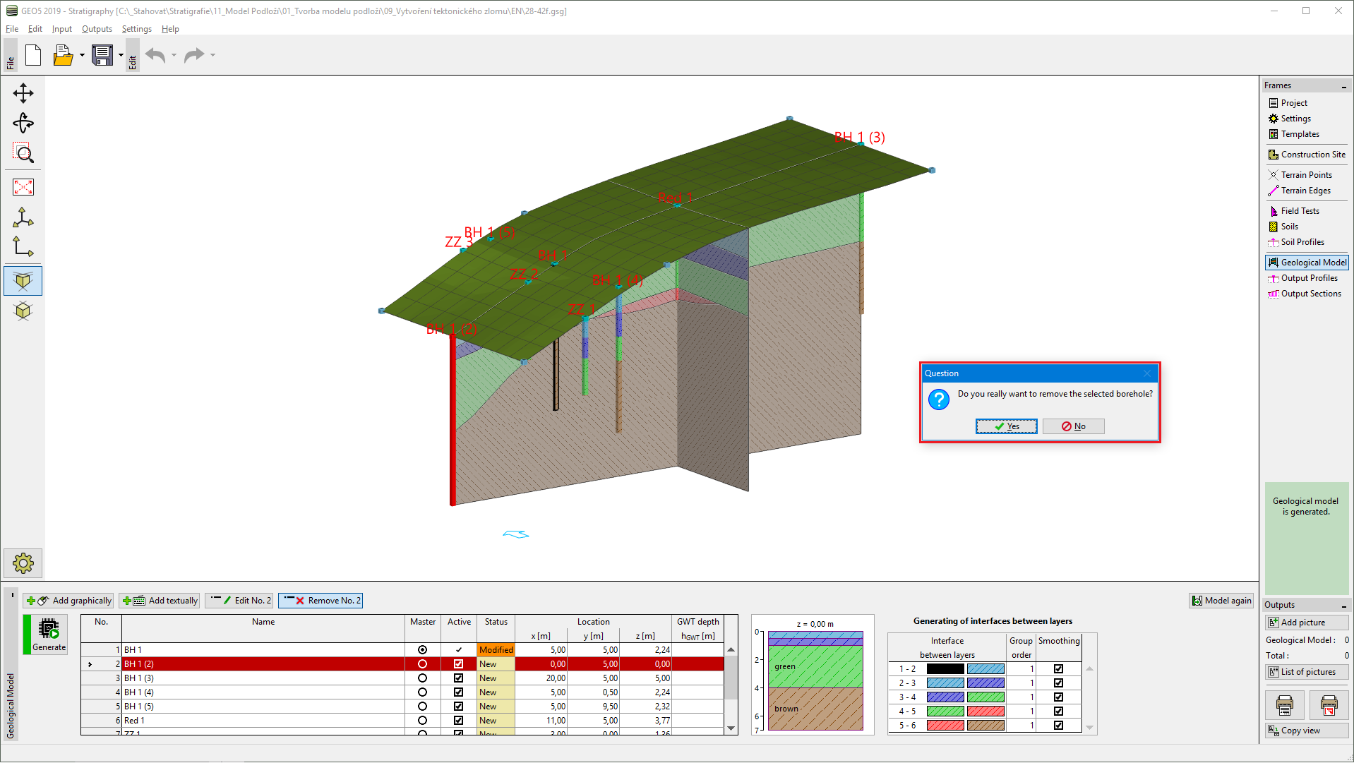 Removing of assistant boreholes in area in front of fault
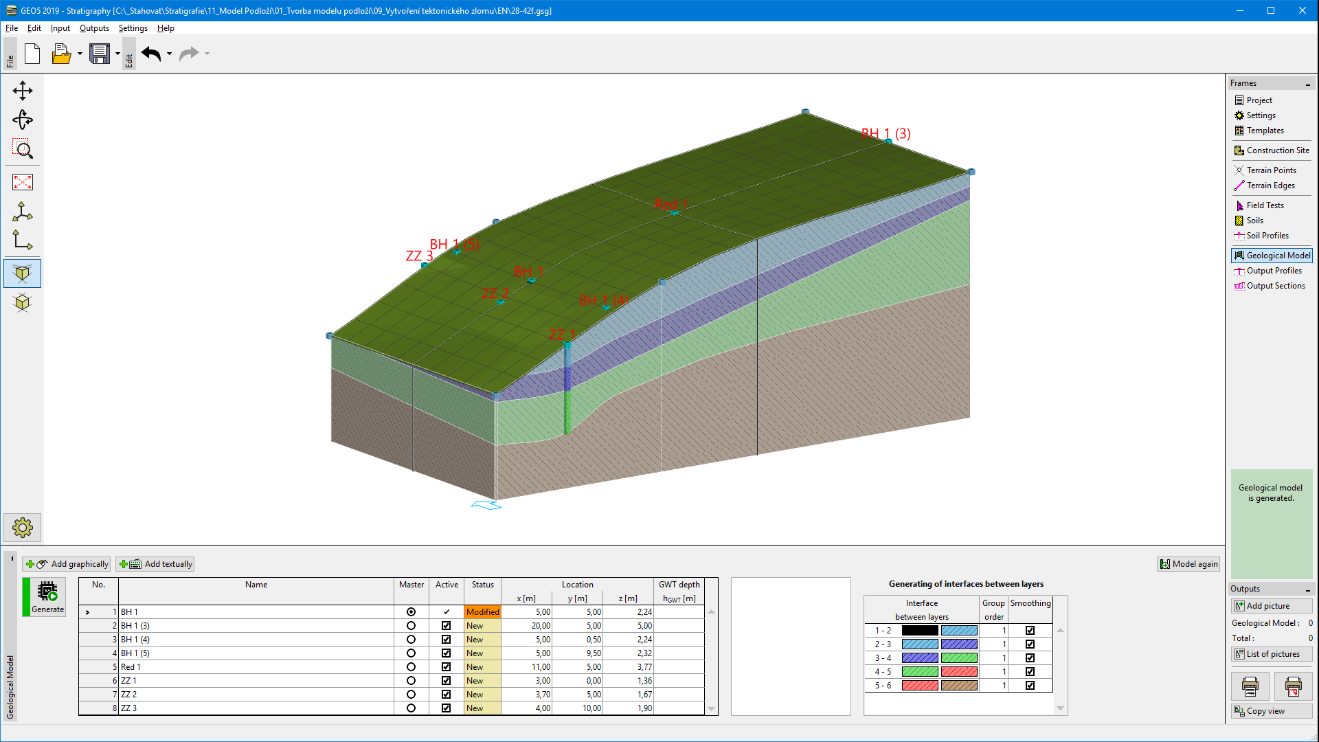 Geological model after input of fault on the terrain
Now the model is ready for creation of area in front of the fault. We regenerate the model and enter two new boreholes: Area 2 (coordinates [0; 0]) and Area 2(2) (coordinates [0; 10]).
We modify both boreholes using "Edit" button. We define interface of fault (layer 1) in depth of [20 m], other layers have location of interface "not defined". Modified borehole Area 2 looks as follows:
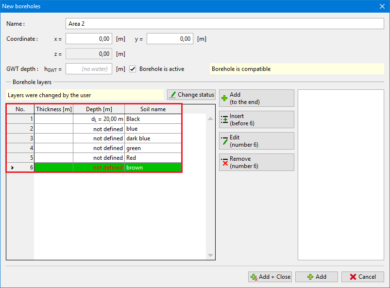 Input of fault in depth
We confirm an input by "Add" button and enter second borehole (Area 2(2)) in coordinates [0; 10].
Then we generate a model - the fault is visible. The area in front of the fault is shown in grey.
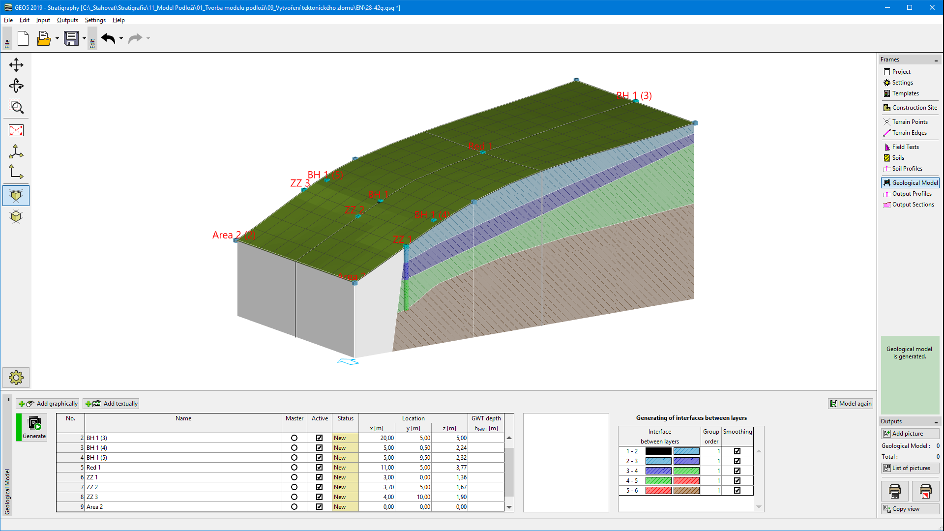 Created geological fault
Now it is necessary to define layers in the area in front of the fault. We select one of boreholes in front - Area 2 or Area 2(2) and add layers above the fault (using "Insert" button). We define thickness of layers in this borehole -3 m - yellow, 1 m - blue, 1 m - dark blue, 1 m - green, 1 m - brown. In next step it is necessary to add new defined layers to the master borehole using "Add upper layers (into master borehole)" button. Modified borehole Area 2 looks as follows:
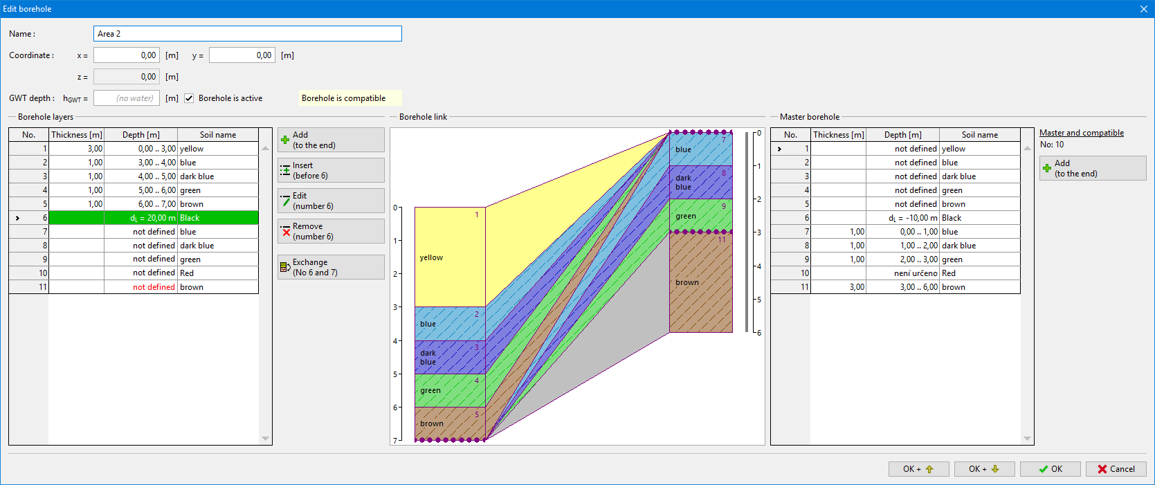 Input of layers into the area in front of fault
After generating model, it looks different than we supposed - new entered layers overlay entire model (also behind the fault).
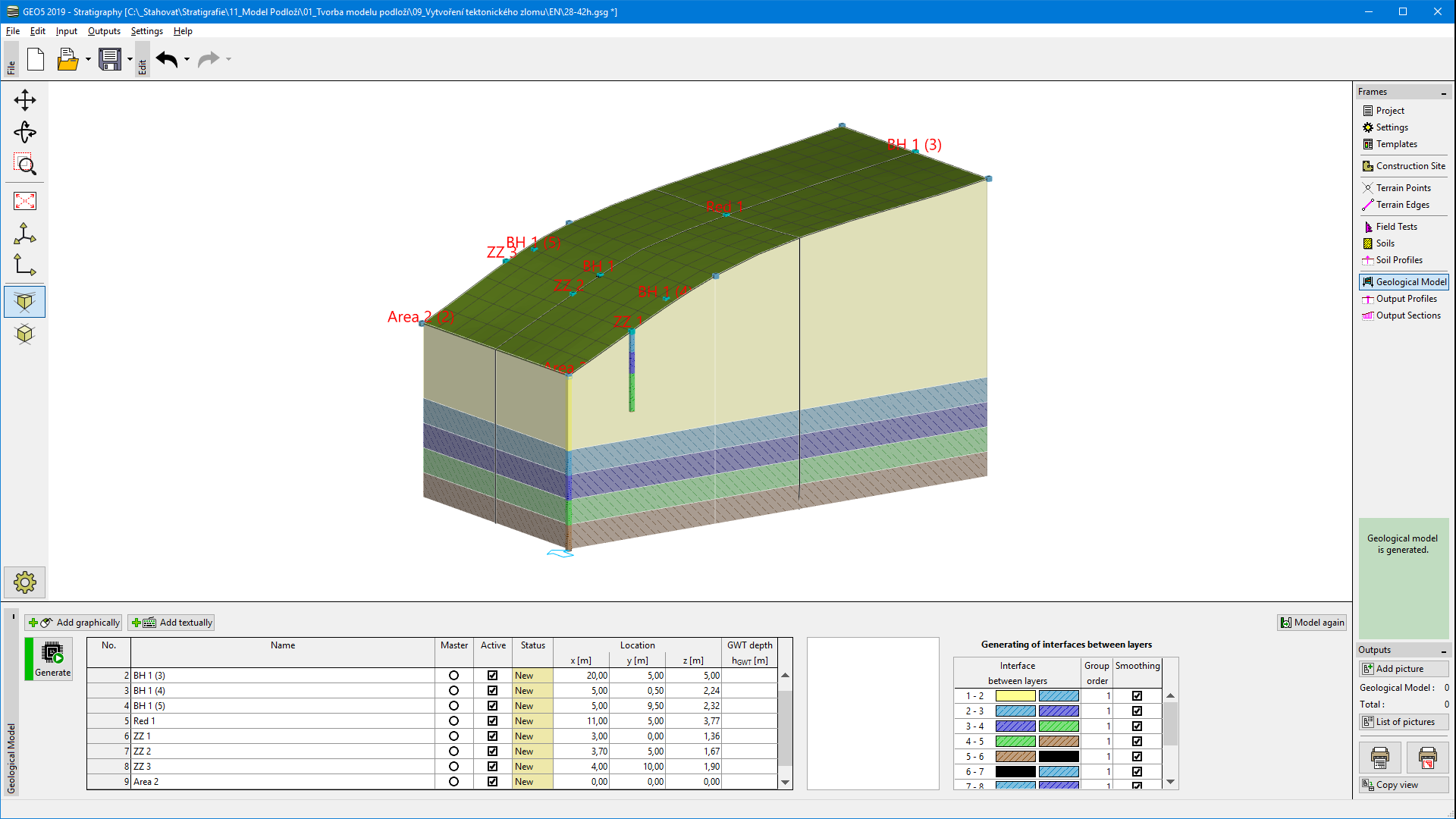 Generated model with wrong order of layers generating
It is possible to solve this problem using changes in order of layers generation. Firstly, we generate fault (row 6-7 with black rectangle on the right side) and layers behind the fault (7-8...etc). We leave a "Group order" as "1". Layers in area in front of the fault are in group "2". The fault (row 6-7 with black rectangle on the right side) is usually straight - we do not use smoothing here.
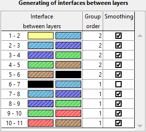 Group order of interfaces between layers
The model is created.
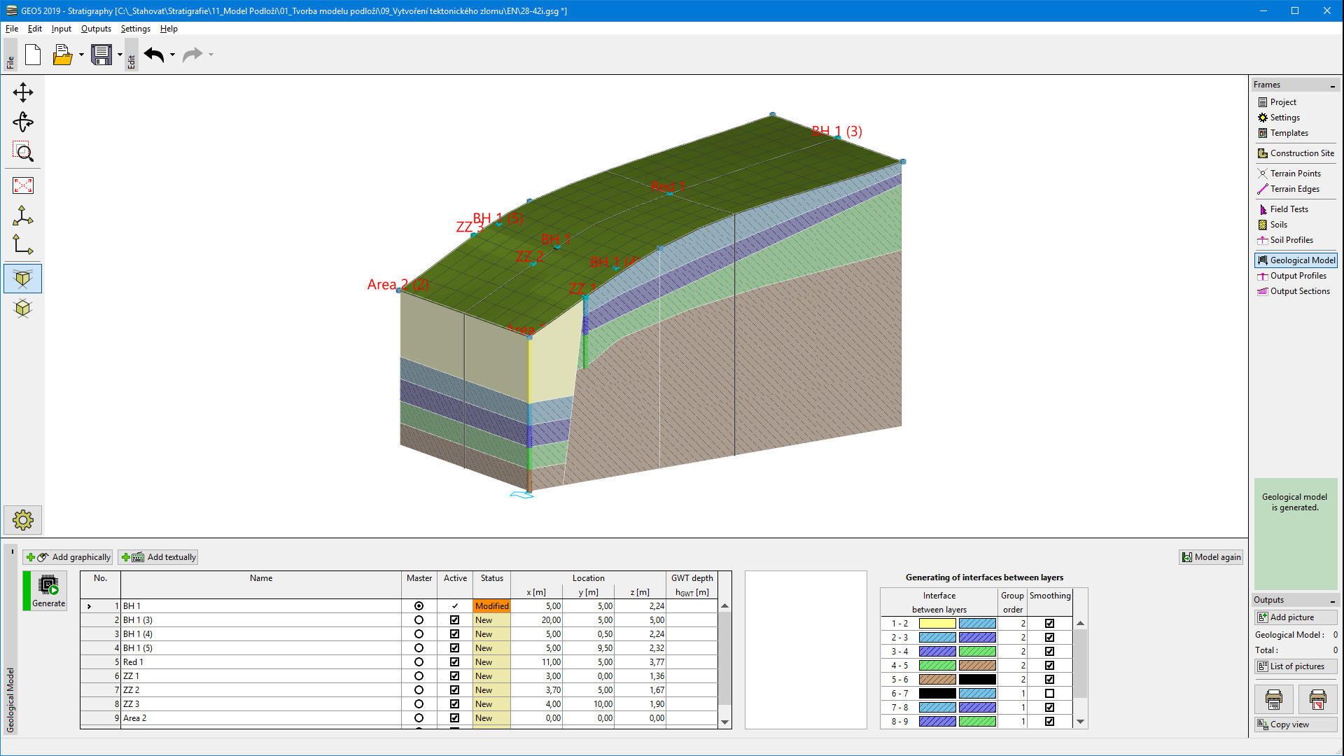 Final model
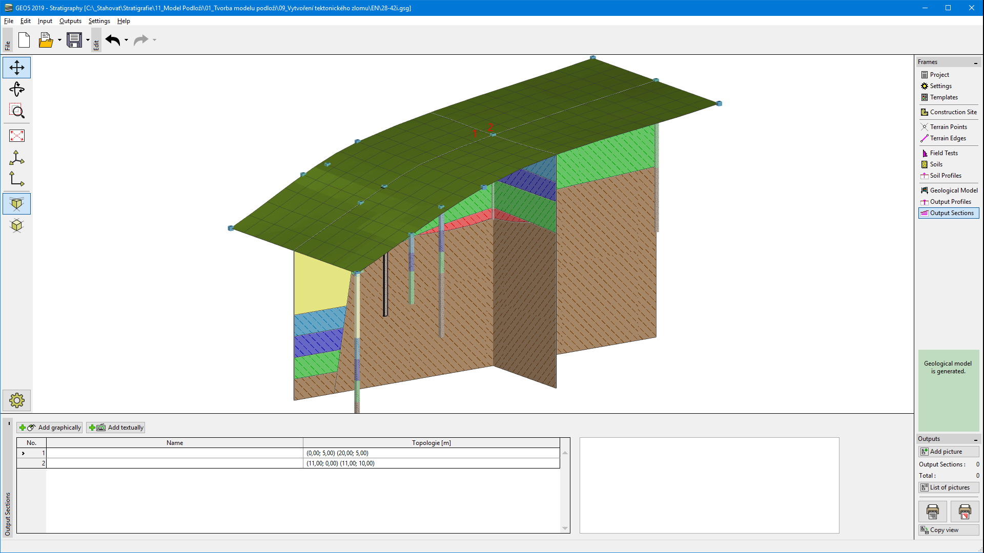 Final model - cross sections