This section contains parameters related to designing splices that the program automatically inserts into the structure when the length of the member exceeds the maximum stock length of the timber.
Percentage of bay, move splices from details | - v - in this mode, the splices are inserted in a position that is determined by the percentage of bay span (the position is editable, the default value is 25%). This allows the splices to be inserted in locations where the minimum bending moment is expected. If a splice comes out near a heel joint, upper joint, apex, or hip joint, the splice will automatically move to the other side of the bay. This avoids collision with plates in significant joints.
|
Percentage of bay, move splices from details on bottom chords | - this mode is similar to the previous one, but the proximity of a significant joints is checked only on the bottom chord
|
Percentage of bay | - a mode where the splice is also inserted at a position defined by a percentage of the bay length, but the proximity of the significant joint is not checked at all
|
Percentage of bay, move splices from first bay | - if this mode is selected, the splices are also inserted in a position that is determined by the percentage of the bay length. However, if a splice occurs in the outer bay, the program will automatically move it to the second bay.
|
According to maximum timber length | - the program inserts the splices so that the individual piece of timber match the stock lengths in the timber database as much as possible. Thus, in this mode, the position of the splice in the bay is not taken into account. However, it is possible to define a minimum distance of the splice from the joint that reduces the collisions of nail plates in the structure.
|
Do not create splices | - the program does not automatically enter the splices, it is assumed that they will be entered manually by the user
|
In addition to the basic method of inserting splices, the following settings can also be used:
Respect symmetry | - if this setting is checked, the program inserts splices symmetrically on the members intersecting the symmetry axis (usually the horizontal top and bottom chords). The structure can thus be completely symmetrical, but in some cases there are more splices in the structure than would be necessary
|
Start at end points for horizontal members | - by default, splices on horizontal members are calculated from the middle to limit the splices at the point of greatest axial force. If this setting is used, the splices are inserted from the eaves details. This prevents collision of the splice with the eaves detail.
|
Start at the top for inclined members | - by default, the splices on sloped top chords are inserted from the eaves detail, i.e. from the point of greatest normal force. If this setting is used, the program will proceed in the opposite direction
|
Allow splice in the middle of bottom chord | - if this setting is checked, the program can insert the splice in the middle of the central bay (i.e. in the axis of symmetry) even if it contradicts the rules about the placement of the splice in percent of the bay length.
|
Divide member in splice | - the program will model the splice as an absolute joint, thus splitting the continuous member into two. Different section depths can then be specified for the newly created members. In the automatic design mode, it is necessary to pay attention to the "Respect maximum depth" setting for the given member type in the "Members" part. If it is checked, the program will not design different depths in automatic mode, as it will insert the maximum depth everywhere.
|
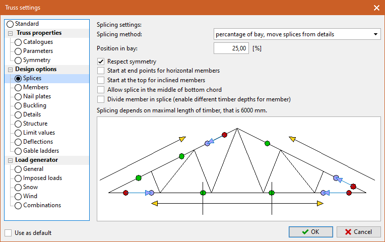 Part "Splices"