Version 17
New features in the version 17:
Two parallel versions
Truss4 now supports two parallel versions on one computer. In addition to the current version (version 17), the previous version (version 16) will always be available. Both versions can be installed using the installer from our website:
https://www.finesoftware.eu/roof-truss-design/install/
The installer contains a menu for selecting a version. If version 16 is uninstalled during the installation of version 17, it can be reinstalled using the installer mentioned above. When working with two versions, the rules of the Windows operating system regarding file associations must be observed. In most cases, Windows associates files with the version that was installed last.
New modelling core in Truss 2D
A new modeling core was added in the "Truss 2D" program. This model replaces existing mounting of the structure. The new model significantly expanded the possibilities of truss topology, most of limitations no longer appear in the software. The main changes are:
- Unlimited number of members in joint
- Eccentric connection of any member into a joint
- Unlimited number of cuts at the member ends, both convex and concave ends are supported
- Manually defined cuts
- Joint and member codes are used only for assignment of pre-defined details (eaves detail etc), the insertion of automatic loads and other calculation parameters (buckling etc.). Codes does not affect feasibility of the design.
You can switch between old and new modelling mode in the tab "Mounting" of the "Project/Truss settings":
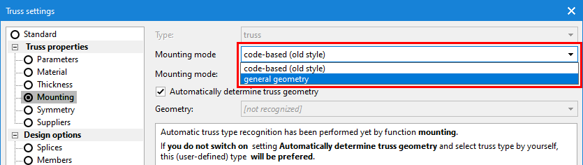 Switching between old and new modelling mode
The main improvements of the new modelling mode are:
Eccentric connections of members
Previous versions supported eccentric connections of members only in a few clearly defined cases (eaves height entered for rafter, web connections, offset of the edge vertical). The eccentric connection can be defined for the beginning and end of each member now. The eccentricity can be entered in the "Topology" tab of the "Member properties" and consists of two components:
- Automatic eccentricity – this component contains the above-mentioned eccentricities depending on the properties of member or detail. This includes the eccentric connection of rafter into the eaves detail, the offset of the edge vertical, the alignment of the webs according to the chord height and the eccentricity caused by the alignment of member to another member or line.
- Manual eccentricity - the ability to move the beginning or end of the member relative to the joint. The offset is entered as a combination of length and orientation. An angle of 0° represents a shift in the direction of the Y axis, an angle of 90° a shift in the direction of the Z axis.
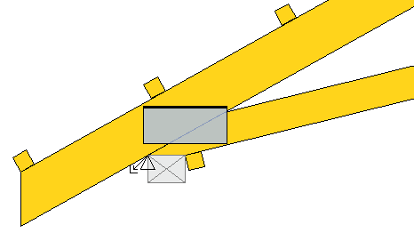 End of bottom chord offset from the joint in the horizontal direction by the width of the support (offset equal to the width of the support, angle 0°)
Both components of eccentricity can be switched off separately.
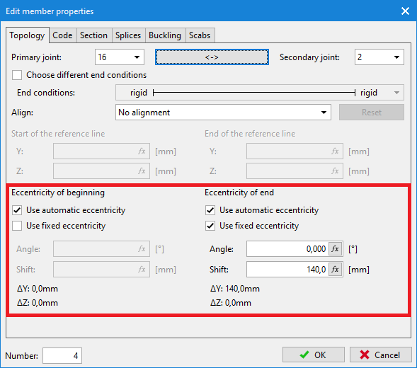 Entering eccentricities in "Member properties"
New concept for superchords
Superchords are no longer a property of the main member but are entered as separate members. As a result, they are no longer limited by additional topological rules. The superchords can now be placed on the inner and outer edge of the main part, member depth is not limited, and the additional member can even extend beyond the main member.
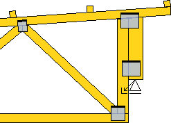 Detail showing a member aligned to the outer edge of vertical
Superchords are entered using the standard "Add member" command. If the start and end points lie on the same member, the program automatically aligns the additional member to the main member. The edge for alignment can be changed using the "Align" setting in the "Topology" tab of "Member properties".
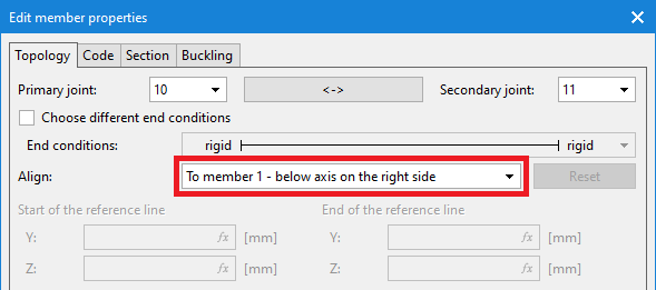 Alignment of member to the edge of another member
Manual cuts in joints
Cuts in any joint can be modified manually. The user interface for these modifications is placed in the "Joint edit" tab of "Joint properties".
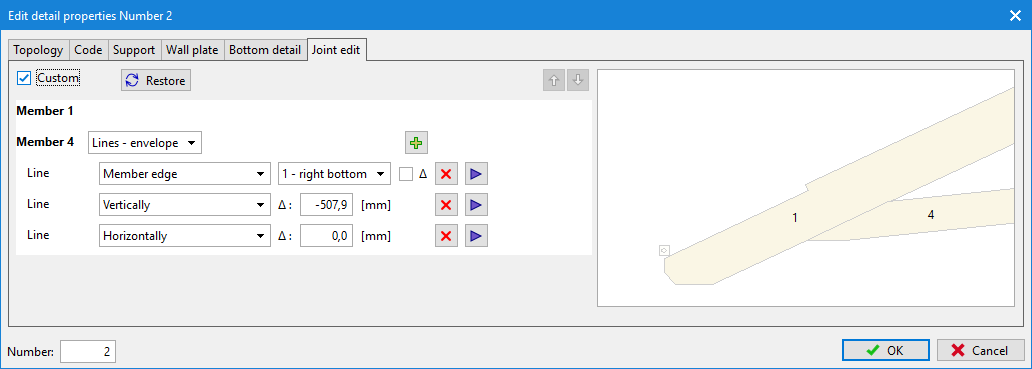 Editing cuts in detail
The program cuts members in the joint automatically according to the selected detail properties (cutting diagonals, etc.) and according to the priorities of individual members (outer members have a higher priority than webs). However, you can enable manual cut entry by checking the "Custom" box. Cuts are entered for each member separately, there are three ways of input:
- Lines - envelope – cuts at the end are entered without distinguishing the order. Each cut can be linked to different reference objects (joint, member edge, intersection, etc.). In this way, any convex member end can be created.
- Lines - order – member end is created with the help of ordered list of cuts. Both convex and concave ends can be created using this mode.
- Polygon - An option to specify geometry using individual polygon points
It is assumed that the user interface for manual input of cuts will be improved in the following versions.
Remove any nail plate
Any nail plate can be deleted using the "Remove nail plate" tool in the context menu of the joint.
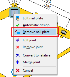 Nail plate removal tool
If the automatically inserted nail plate is removed, it can be restored using the "Generate nail plate" command in the context menu of the joint.
Option to insert an additional nail plate into the structure
You can insert a nail plate anywhere in the structure using the "Add nail plate" tool in the context menu of the workspace. This nail plate corresponds to the non-structural plates in previous versions, but it is part of structural analysis now.
Modified window for editing nail plates
The nail plate editing window has been redesigned. The most significant change is the ability to edit more plates without having to close the window. If a dwg/dxf construction layer is loaded, it is also displayed automatically in this window.
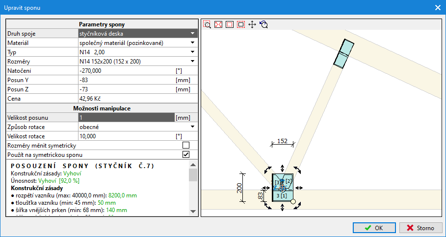 New window for editing nail plates
General connections
Any nail plate (manually inserted or automatically created in the joint) can be converted to "General connection" in the "Edit nail plate" window. In this way, any structural connection (bolt, nail, etc.) made on site can be considered during structural analysis. The joint geometry in the structural model is based on the position and dimensions of the defined rectangle. The joint stiffness is entered in the form of springs kx, ky a kφ.
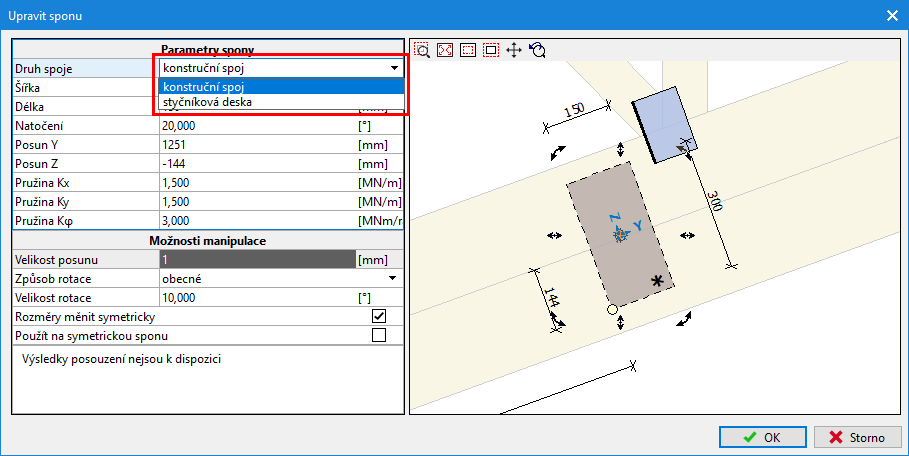 Input of general connection
The general connection only creates the connection of members in the structural model, no verification of the connectors is performed.
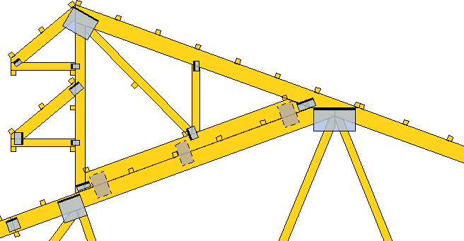 Three general connections are connecting additional part to the main truss
Changes in structural design
Structural analysis was adapted for the new modelling core. The main changes are:
- In combination with the new modeling core, it is no longer possible to use simpler types of structural models ("out of center-lines" and "eccentricities in joints"). The recommended static scheme now is a static scheme according to DIN EN 1995-1-1
- In addition to the fixed and pinned connections of member ends, it is also possible to use semi-rigid connections. This method of modeling is the only one allowed in most European countries (Germany, France, Great Britain, Scandinavia)
- Reduction of shear forces in the vicinity of supports according to 6.1.7(2) of EN 1995-1-1 is used in the verification of members
- In-plane buckling is not verified close to the joints
- Bending moment reduction is performed in the inner joints on chords
Two new topological tools
Two new tools have been added:
- Disconnect member (context menu of member) – if the member is connected to the joint eccentrically (for example, a rafter in the eaves detail), the program creates a new joint at the point of member origin, reconnects the part into it and creates a new member between both joints.
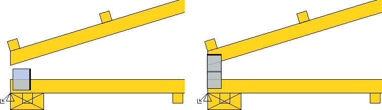 Eaves detail before and after using the "Disconnect member" tool for the rafter
- Merge joint (context menu of joint) - If two joints are located close to each other so that it is not possible to create a member between these joints, it is possible to merge the joints into one using this tool. The "Merge joint" tool is currently only available in the context menu of the joint in the "Truss 2D" program.
Centre of gravity and lifting points on the workspace
Marks for the center of gravity and the lifting points on the top chords can be switched on in the dimensioning settings.
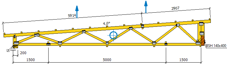 Centre of gravity and lifting points
Merging windows with joint and detail properties, respectively member and cut-piece properties
The "Joint properties" and "Detail properties" windows have been merged into one "Joint Properties" window. The same adjustment was also made for the "Member properties" and "Cut-piece properties" windows. This adjustment greatly simplifies manual truss adjustments.
Construction layer in the program Truss 2D
The drawing in *.dwg or *.dxf format can be used as a construction layer during modeling trusses. This function is identical to the already existing tool in the "Truss 3D" program.
Extended saw settings
The settings for exports to automatic saws have been extended in the "Application options". In the new "Export file formats" tab, user can set, for example, the maximum number of cuts per member end for each format and how concave cuts are to be transferred to the saw. The same tab also contains an option to set the destination folder for saving export files.
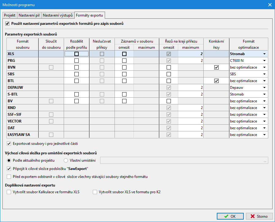 New tab "Export file formats"
New tool for joint shift
The new tool "Move joint" was added into the local menu of joint. This tool is used to quickly move the joint in the direction of the member by the specified distance.
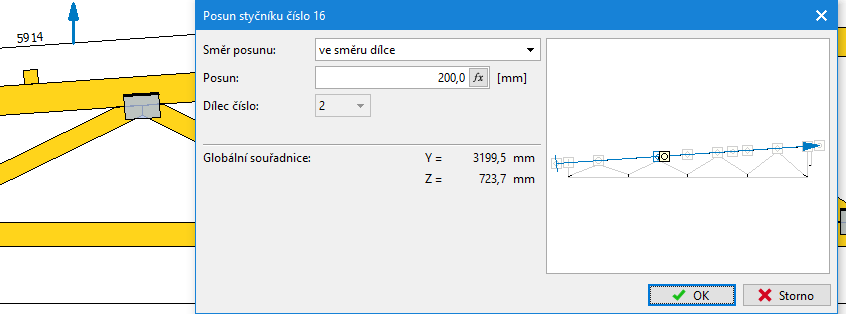 Window "Move joint"
Combination rules for photovoltaics and solar panels
The new load case type "Photovoltaics, solar panels" has been added to the list of available load types. These load cases are a permanent load, but load combinations without these load cases are also verified during the truss design. The current version only solves combination rules, loads in these load cases must be entered manually.
Option to turn off watermark in outputs
It is now possible to turn off the watermark in the printing window. This setting can be used in cases where only informative documentation of unverified or unsatisfactory structure is printed and where the watermark can be a disturbing element. The setting is in the header of the document tree, where the verification status is also newly displayed.
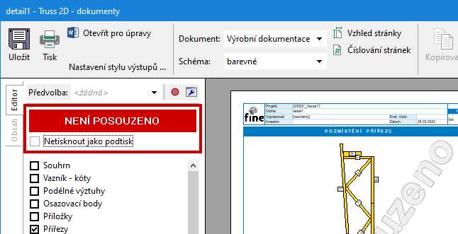 Option to hide watermark