Version 14
New features in the version 14:
Improved support of scaling in Windows
The software contains better support of UI scaling in Windows which is used mainly in combination with hi-res screens. All UI components in truss software (e.g. text, icons, menus, symbols) are scaled according the Windows’ settings.
New toolbars
New version of toolbars was developed. New toolbars are able to combine more components and icons with different sizes.
New system of graphical selections
The system of object selection in workspaces was changed completely. The new system corresponds to the work in CAD applications. It is possible to select more types of objects (e.g. walls and trusses) in the same time. The selection from left to right selects only objects which are completely in the selected area. The selection from right to left selects also objects which meet the selected area partially. The selected area has dashed boundaries in this case.
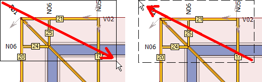 Selection from left to right selects truss positions 21, 24 and 25. The selection from right to left selects all displayed trusses and also both walls.
The selection mode (adding to selection or deleting from selection) is controlled using the keyboard. This eliminates the need to select an appropriate mode in the toolbar. The basic selection without any keyboard input is used to add objects into the selection. If the “Shift” key is held during the selection, the program removes objects from the selection. When the “Ctrl” key is pressed, the program is inverting the selection (the selection of already selected objects is canceled and the not selected objects are selected).The graphic selection can be canceled at any time by pressing the “Esc” key. The toolbar with the choice of selection area shape (line, rectangle, rhomboid) is still available.
Object snap tracking in 2D input
The object snap tracking can be now used during the input in the 2D workspace. If you hold the cursor for a longer period of time above the snap point during the input, the program marks it with a cross and starts to consider it as a new start of polar tracking.
![]() Symbol of a new object for polar tracking
Symbol of a new object for polar tracking
This function can be used, for example, to specify a point which uses an X-coordinate from one point and a Y-coordinate from another. It is necessary to hold the cursor over the first and then over the second point, in both cases until the symbol of tracking point appears. After that, it is possible to insert a new point into the intersection of rays which come from tracking points.
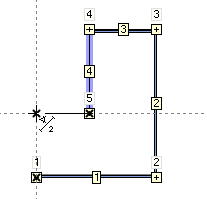 Input of wall using object snap tracking
The number of points for polar tracking is not limited. This way of input speeds up the work with the software and reduces the work with construction lines.
Merged window with settings
Windows “Truss settings”, “Design option”, “Load generator” and “Analysis options” were merged into one window “Project/Truss options”.
Advanced options for nail plate range in the company catalogue
It is possible to the range of nail plates for certain applications in the tab “Advanced options” of “Nail plates assortment” window. For example, it is possible to disable certain nail plate type for splices.
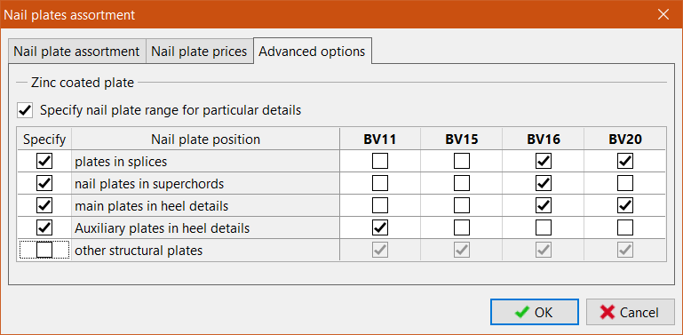 Advanced options of nail plate assortment
Export files for CNC saw machines Randek and Hundegger P8/10
The software is able to create controlling files also for CNC saw machines Hundegger P8 and P10 (file extension *.bv) and Randek (for example SPL728).
Saving documents into *.docx file format
Output documents can be saved also as *.docx files (XML file format of MS Word).
New 3D engine
The 3D engine was completely rewritten according to the latest OpenGL specification. Result of this change brings faster and more stable 3D environment. Manipulation with 3D model is now smooth and fast. New version of OpenGL engine solves all known issues connected with 3D interface in old versions of the software.
Active workspace in Truss 3D
2D and 3D workspaces are active and can be used for direct editing of objects. Double-click on the object (wall, truss, member etc.) opens the window with object properties. Single click opens a context menu with the most frequent commands related to the object. The context menu differs according to the object type.
There is also dedicated context menu for the workspace (click outside any object).
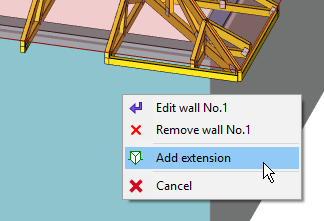 Context menu for wall
It is possible to work with more types of objects (e.g. walls and trusses), it isn’t necessary to switch modes in the tree menu anymore. This context menu also contains dedicated functions for work with selected objects.
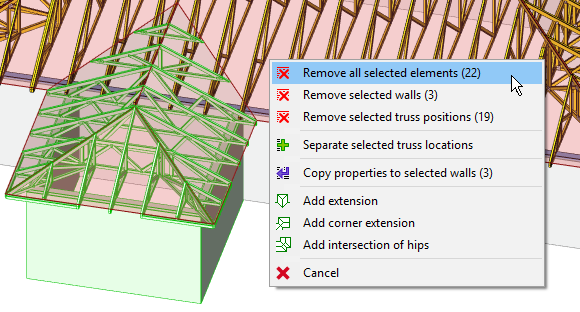 The context menu for the workspace contains also functions for selected objects
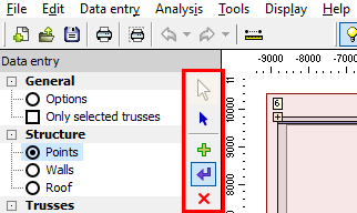
Modified tree menu in Truss 3D
The number of items in the tree menu was reduced significantly due to active workspace and the ability to edit more types of objects in the same time.
Graphic modes
The toolbar with graphic modes which was placed on the right side of the tree menu was completely removed.
Since the workspace provides an option to edit all objects in the same time, the graphic modes are useless.
 Toolbar with graphic modes in the version 13
Automatic recognition of identical trusses
A new feature for automatic recognition of similar trusses can be used when creating new trusses or upgrading existing ones. If the “Search for identical trusses” option is selected in the upper left corner of the tab “Truss” of the “Properties of truss location” or “Properties of truss group” window, the program tries to find and use an existing truss with identical geometry instead of creating a new truss type. Searching is performed when the user runs the “Create truss” or “Create all trusses” command.
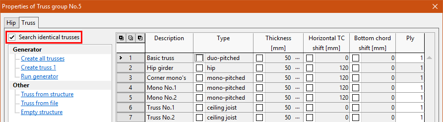 Setting “Search identical trusses”
This function is an automatic alternative to the command “Truss from structure” where the truss type has to be selected manually. If this setting is disabled, the program behaves as in earlier versions.
Specify the position of the last mono pitched truss on the wall
The position of the last mono pitched truss on the wall can be specified in the hip properties. This value defines positions of all short mono pitched trusses connected to the corner girder. If the same value is entered for hips with different spans, these trusses will be identical in all hips.
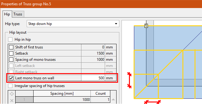 The setting “Last mono on wall”, the figure shows geometric meaning
Export IFC
The 3D model of the structure can be exported into the *.ifc file. This file is used for building information modelling (BIM).
Tool for fast input of splices
A new tool “Add splice to member bay” has been added to the context menu of a member in the part “Results” of the tree menu. This tool is able to insert easily the splice and specify its parameters:
- Choice of position input – the splice can be entered exactly according to the cursor’s position or the tool will respect the percentage of bay length specified in the “Project settings” part “Splices”.
- Splice type – splice type can be “fixed” or “pinned”, default values are based on the parameters specified in “Project settings” part “Structure”
- Modification of position – final position can be fine-tuned with the help of all options available for relative joints.
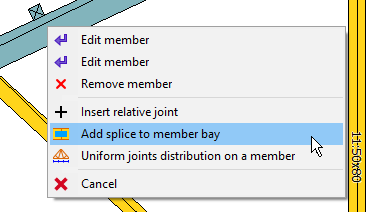 New tool “Add splice to member bay”
New tools in the context menu of the truss in the part “Results”
Two tools “Renumber structure” and “Remove idle rel. joints” were added into the context menu of the truss in the part “Results”. These tools were originally available only in the program “Truss 2D”
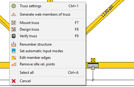 New appearance of the context menu in the part “Results”
Modifications of the truss table
A new column “Compression in joints” was added into the truss table in the part “Results”. This column corresponds to the setting “Compressive forces in joints” which is located in the part “Standard” of the window “Truss settings”. The frame “Details” on the right side of the table contains basic price details (timber volume, nail plate area, price).
Changes in the tree menu of Truss 2D
The tree menu was reduced and it does not contain collapsible parts. These changes significantly improve the speed of work with the program. Main changes are:
- The menu does not contain non-active items. These parts (headings “General”, “Topology”, “Truss” etc.) were converted into active items. The bottom frame in these parts contains tabs with corresponding objects
- Dedicated tools for deleting and editing objects (e.g. “Edit joint”) were replaced by general tools “Edit” and “Remove”.
- The tools in the parts “Topology” and “Truss” were merged into one list
- Some functions from the tree menu (e.g. “Rel. to abs.”) were moved into corresponding context menus (conversion of the relative joint into the absolute one can be found in the context menu of the relative joint).
- The content of the part “Truss” was moved into the part “General”, the content of the part “Structural analysis” was moved into the part “Results”.
Active workspace in Truss 2D
The program “Truss 2D” has also an active workspace with context menus and an ability to work with more types of objects in the same time. The fundamental principles were copied from “Truss 3D”, part “Results”.
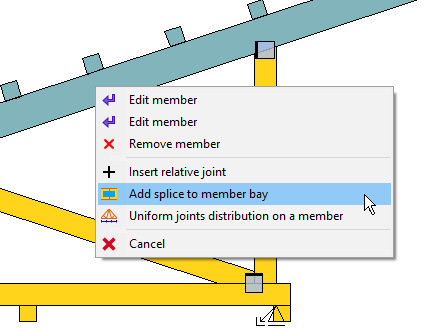 Example of context menu: the menu for a member
Changes in tools
Tools in the parts “Topology” and “Truss” were merged into the one list “Tools” which is located in the part “Topology” of the tree menu.Some tools were removed as the abilities of new workspace are much wider and these tools became useless.The most common tools are available also in the new toolbar “Tools”. This toolbar also contains buttons for opening “Truss settings” or for measuring tool.
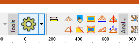 Toolbar “Tools”
New eaves detail “Vertical with cantilever”
The “Truss generator” contains new eaves detail “cantilever”. This detail can be used in cases when the cantilever is higher than the end of bottom chord. Inputs for this detail are the cantilever length, eaves height and cantilever height or height of the vertical web. Meaning of these dimensions is shown in the following figure.
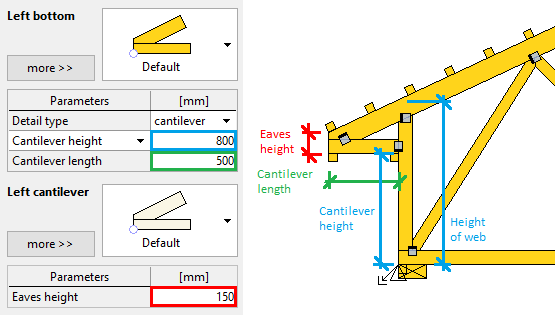 Meaning of particular inputs. The cantilever height and height of the vertical web are alternative inputs
This detail is included only in “Truss generator”, it isn’t available in the “Wall properties” in “Truss 3D”. The detail with edge vertical and overhang of top chord should be specified in these cases. Such detail can be easily converted into the new one by changing the detail type and input of eaves height in “Truss generator”. The rest of inputs will be filled automatically.
New detail for supports on the bottom chord
New detail type was added for absolute joints on bottom chord. Vertical web is extended to the lower edge of the bottom chord. This detail is helpful mainly for joints with supports as it provides much better capacity in compression.
The detail is available for joint codes 15 (bottom chord, corner left) and 16 (bottom chord, corner right). As the most of joints on bottom chord are the relative ones, it is necessary to convert such joint into the absolute one with the help of the tool “Relative to absolute” first.
The vertical web with code 2 (vertical web) is extended automatically. If there are only inclined webs (code 3) connected into the joint, the smallest angle between web and vertical line is the decisive rule.
The topology of bottom chord is not limited. The bottom chord can be horizontal, inclined or there can be a change of angle in the joint.
The web can be extended under the bottom chord. The support can be also specified at the end of this extension.
The compression in the support is calculated according to the chapter 6.2.2 of EN 1995-1-1. This analysis provides significantly higher bearing capacity comparing to the standard supports with continuous bottom chord.
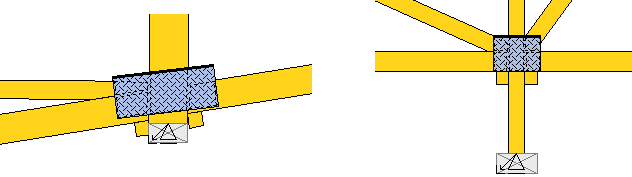 Examples of the new detail
Different detail for small angles between webs and chords
The different cutting style can be specified for small angles between webs and chords. The default cutting style usually provides very long cuts in these cases which complicates the production.
The new item “Web cutting mode for small angles” was added into the part “Details” of the window “Project/truss settings”. If the value “Different cut” is set to “YES…”, it is possible to specify limiting angle and type of cutting mode (using the button “Modify” in the right part of the window).
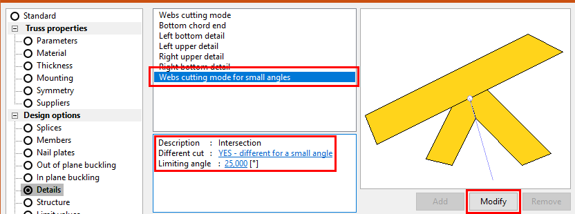 Settings related to the new details
Limiting angle is checked for mounting scheme at this moment. The real angle is therefore usually smaller.
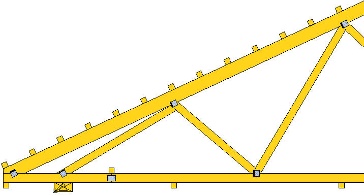 First joint on the top chord has different cuts since the angle between chord and first web is too small
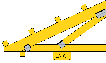
An option to specify number of nail plates in the eaves detail with wedge
The number of nail plates on the wedge can be specified in the properties of the bottom detail. An automatic mode is switched on as a default. The number of nail plates is selected according to the topology in this mode.
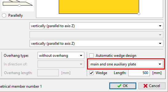 Number of nail plates for a wedge
Do not reduce bottom chord depth in the eaves detail
The eaves detail "Standard" has the new setting “Do not reduce BC depth”. If this check box is ticked on, the software will cut bottom chord only by the vertical cut. This setting is useful mainly in valley when the eaves height is smaller than the bottom chord depth.
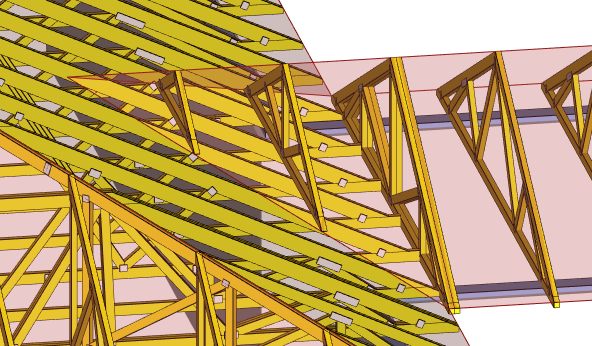 Trusses with new detail in a valley
Extended options for “Edge cut”
The input line “Edge cut” in the properties of eaves detail has extended range of allowed values:
- Positive values – the positive value represents final (remaining) dimension. This way of input is helpful mainly in “Truss 3D” where the top chord depths may differ for particular truss types.
- Value 0 – The cut corresponds automatically to the lower edge of the bottom chord
- Negative values – The dimension of the part which was removed by the cut. This is the way of input which was used in previous versions.
 Eaves detail where the “Edge cut” is equal to 0
Option to switch off all auxiliary nail plates
Auxiliary nail plates are added automatically into eaves details and apex if the joint is not covered by a nail plate properly. Unchecking the setting “Generate auxiliary nail plates” removes all these nail plates from all joints.
Insert splices from the top for top chords
Inclined top and bottom chords have new mode for inserting splices. If the setting “Start at the top for inclined members” is switched on, the software starts with inserting splices on the higher end of the inclined member.