Version 18
New features in the version 18:
Graphical tools for the work with walls in Truss 3D
The "Tools" toolbar that appears for the 2D workspace can be also used to work with selected walls.
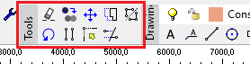 The "Tools" toolbar
Using the individual tools in the toolbar, selected walls can be moved, copied, mirrored, stretched, rotated, extended or cropped.
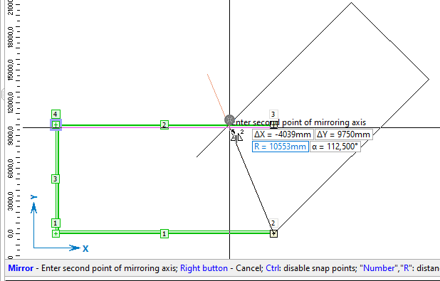 Mirroring walls
These graphic functions currently only work with walls. When creating a copy of a wall, there is no copying of the trusses connected to the wall or the roof planes associated with the wall.
Bulk editing in Truss 2D
The sidebar on the right side of the "Truss 2D" workspace allows user to change the basic properties of selected members, joints and connections (nail plates). This is a faster way of editing than the use of the editing dialogs. The following properties can be changed:
- Members – cross-section, material, code, production part
- Joints - code, support, wall plate properties
- Connections (nail plates) - connection type, nail plate type and size, automatic design option, rotation, production part
If more than one type of structural element is selected, it is possible to select the element type for edit in the drop-down list in the sidebar header. In addition to members, joints and connections, the "Drawing" option is also available in the list. This item allows user to edit lines, dimensions, text, geometric objects, etc. drawn using the tools in the "Drawing" toolbar.
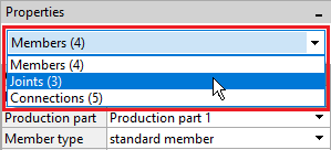 Selecting the type of element in the panel header
The properties of connections (nail plates) are only available for trusses created using "General geometry".
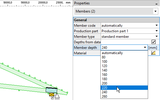 Bulk editing of the height of the part
Dividing trusses for production in general geometry
In the new "General Geometry" modelling core, it is now possible to divide trusses for manufacturing or transporting reasons. The way of working differs significantly from the truss cuts used in the original modelling core. Thanks to the new concept, many limitations were removed. The main changes are:
- The joint lines between the production parts can be arbitrarily broken
- Trusses can be split vertically and horizontally at the same time
- The program no longer automatically cuts any members into particular sub-members
A new node "Production parts" has been created in the "Truss 2D" tree menu for the work with production parts. The table in the bottom frame shows the list of production parts. When you click on a part in the table, all the elements (members and connections) that belong to that part are highlighted on the workspace.
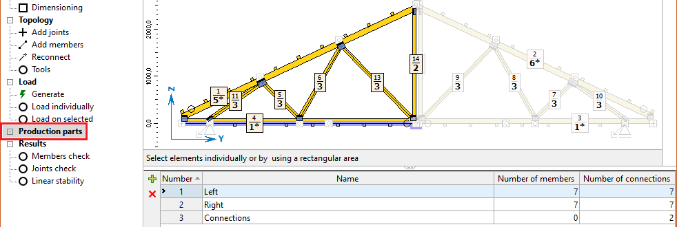 The "Production part" node of the tree menu
The work in this section differs significantly from the work with construction sections in previous versions. In the default state, the truss has only one production part and is assumed to be produced in its entirety. If the truss needs to be split for production or transport reasons, the truss topology must be modified accordingly, as the program no longer performs automatic cuts. Thus, for example, absolute splices should be entered on chords. These absolute joints divide members into separate parts. A "general connection" can be used instead of a nail plate in these joints.
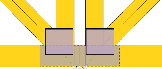 Detail of the bottom chord divided by an absolute splice
If the truss topology is already complete, it is possible to switch the control tree to the "Production parts" node and divide the truss into parts. The simplest procedure is to select all the members and nail plates (highlighted in green) of the intended production part and then use the "+" button next to the production parts table to create the new part. The selected elements are automatically inserted into the new production part.
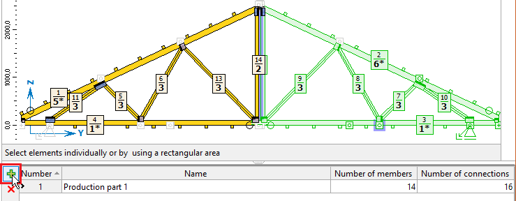 Creating a new production part for the selected members and nail plates
The newly created production part can be named in the table. The assignment of a member or nail plate to a specific production part can be changed at any time in the "Properties" sidebar.
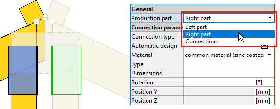 Changing the production part for selected nail plates
A production part can be deleted by clicking the "X" button on the left side of the table with production parts. All members and connections from this deleted part will then be automatically assigned to the first production part in the list.
This way of working is used for the new structure model ("General geometry").
Extended options of infill hip
In the "infill hip", it is possible to select a new arrangement of the mono pitched trusses in corners. If the setting "Alternate corner courting" is used, the program alternately shortens the courting on both sides of the corner rafter. In this way, sketches with significantly overlapping bottom flange can be avoided.
 The new configuration in the Infill hip
Option to set default drawing layers
In Truss4, it is possible to predefine a list of layers that are automatically created in a new project. The corresponding functions are placed under the "Default" button in the "Layers" window. The "Save layers as default" function saves the current list as the default one for new projects. The "Use default layers" function loads the layers from the default settings into the current project.
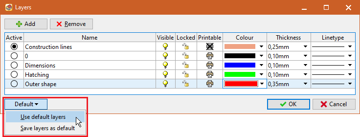 Functions for the default list of layers
Export of the 3D model into BTL format
Export of the spatial model to the *.btl format has been added. This file can then be loaded into other CAD programs for timber industry. The option to create a 3D *.btl model is located in the "CAD formats" window, which is accessible via the main menu, section "File" - "Export" - "Structure".
New export files for CNC machines
The export options for CNC machines have been extended:
- *.xml (Robogenix EasySaw) and *.mxf formats have been added
- Files for Randek saws now include bevels
- Compatibility of the *.btl file with the Stavelse saw has been resolved
Option to reduce stiffness in service classes 2 and 3
In the "Member properties" on the "Section" tab, a new setting "Reduce stiffness for service classes 2 and 3" has been added. If this setting is checked and the truss is located in service class 2 or 3, the program reduces the stiffness of this member by the factor
![]() \frac{1}{1+k_{def}}
\frac{1}{1+k_{def}}
This reduction is defined in the German National Annex to EC5 for compression members where the permanent component is greater than 70% of the load. Therefore, if the structure is designed for Germany, this rule should be taken into account.
Optimization of the gutter detail model for the design standard SANS 10163-1
For the design standard SANS 10163-1 (South Africa), the eaves detail in the structural model has been modified. The model now corresponds more closely to local practice.