Version 20
New features in the version 20:
Version 18 availability
All existing Truss4 users have access to the version 18 installation, which they can use to view and recalculate projects created in older versions of the program. Version 18 also allows you to change the original mounting of the structure to model using general geometry, allowing older projects to be opened in the current version. Version 18 can be installed at any time using the web installer on this page:
https://www.finesoftware.eu/roof-truss-design/install/
Input of attics
Using the "Add attic" tool in the tree menu, you can enter the shape of the attic that should be created inside the structure. Input is performed on the 2D workspace.
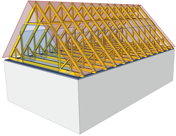 Structure with attic
The attic is entered as a closed polygon, both snap points and numeric entry can be used in the input. Once the space has been entered and then selected, it is possible to edit the attic parameters such as the type, description in the ground plan and load in the "Properties" sidebar on the right.
Three types of attic are available:
- Attic space - it is a regular living space created with the help of attic trusses. It is possible to define the attic height and there is also an option to terminate the bottom chord.
- Storage space - space is created with the help of duo-pitched trusses with storage area.
- Loaded area - this type represents the area with additional load inside trusses. The loaded area does not affect the type and webbing of the trusses.
For each attic area it is possible to enter the permanent floor and ceiling loads and also the imposed load.
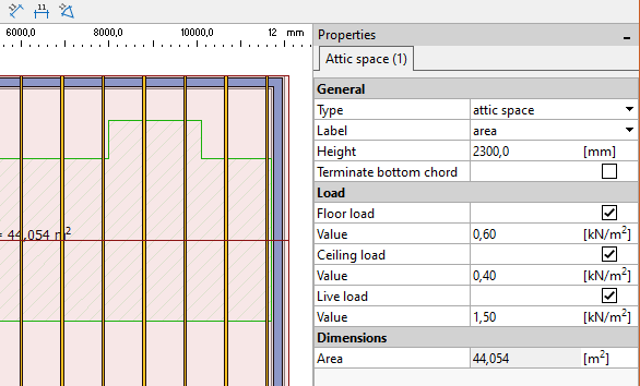 Attic properties
The attics can then be manipulated using graphic tools (e.g. "Move", "Copy"). The shape of the space can also be modified in a dedicated editing mode. This mode can be started either by double-clicking on the space or by using the "Edit attic" item in the attic context menu. In the edit mode, individual polygon vertices are highlighted and can be manipulated. A new vertex can be added by simply clicking on any edge of the polygon. On the contrary, removing a polygon vertex is done by dragging the vertex onto one of the adjacent ones. The editing mode must be finished by right-clicking, pressing Enter, or double-clicking outside the polygon.
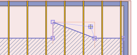 Polygon editing
The attics can also be shown in the drawing. In this case, it is necessary to check "Draw attic" in the drawing settings.
If at least one attic is specified in the project, the corresponding loads (ceiling and floor permanent loads, imposed load in the attic) are disabled in the load generator and the creation of load states is governed by the settings for the attic. If there is no attic polygon in the structure, it is still possible to generate attic trusses or duo-pitched trusses with storage space manually and load them using the generator. In this case, however, it is not possible to define different loads in different parts of the structure.
Loads defined by a polygon in the ground plan
Loads can now be added into manually entered load cases (highlighted in green in the table) with the help of polygons in the ground plan. In this way, it is easy to enter loads on more trusses at the same time.
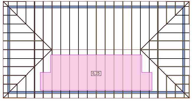 Photovoltaic load defined by polygon
To enter the load, it is necessary to select a manually entered load case in the table of load cases in the "Load" section. Then the "Add area load" tool in the tree menu becomes enabled and it is possible to enter a load polygon in the ground plan.
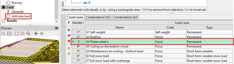 Tool "add area load" for manually added load case "Photovoltaics"
The polygon is entered on the 2D workspace like other graphic objects. Both snap points and numeric input can be used. The polygon must be closed at the end by clicking on the first point. After the geometry has been entered, the polygon can be selected and the basic parameters of the load, such as the position (roof surface or ceiling), the direction of the load and also the value of the load itself, can be defined in the side frame "Properties". A positive load value represents a load in the direction of gravity, while a negative value represents a load in the opposite direction.
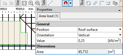 "Properties" bar for load polygon
Loads added to trusses from a polygon cannot be manually modified on the truss afterwards. However, any additional loads can be added to the truss as before. To modify the shape of the load polygon, the same procedures already described for attics can be used.
Graphical tools for trusses
The graphical tools for working on the desktop can now also be used for working with trusses. The following tools are available:
- Copy - creates a copy of the selected trusses, allows multiple insertion. The program tries to find new reference walls or trusses if necessary.
- Move - moves the selected trusses in the specified direction. The program tries to find new reference walls or trusses if necessary.
- Mirror - mirrors selected trusses, allowing both simple manipulation and creation of a copy of selected trusses
- Equidistant - makes a copy of the truss at the specified distance. It is possible to specify the multiplicity of the copy
- Extend/trim -allows the truss to be extended or trimmed. During this manipulation, the truss is connected to a new reference truss or wall and its shape is updated. The trusses to be trimmed/extended can be selected by clicking or crossing out (while holding down the Ctrl key)
Online model of the structure
The ability to create a 3D model of the structure that can be viewed in any web browser has been added to "Truss 3D". In this way, a preview of the structure can be shared easily with the customer.
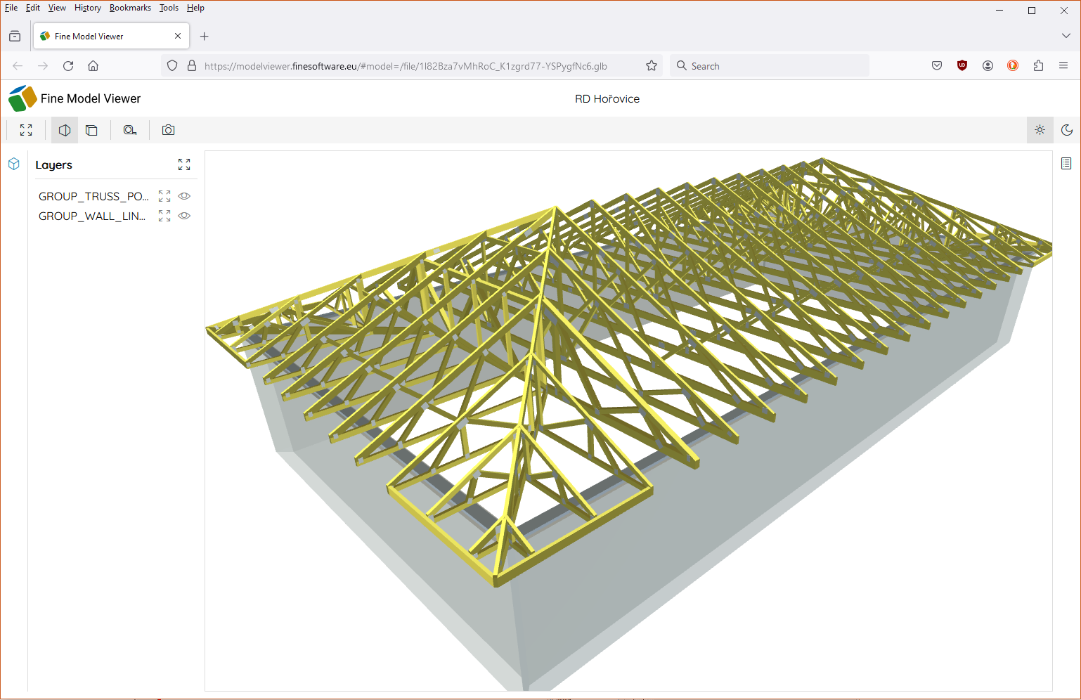 Online model in web browser
The key to using an online model is to specify the repository where the models will be stored. The storage properties are specified in the "Cloud storages" tab in the "Application Options" window. Currently, the only storage that allows model sharing is the "Google Drive" option. The range of supported repositories will gradually expand. In order to use the repository for sharing online models, it is necessary to check "Use cloud folder to share documents online" in the properties and select or create a folder where the models will be stored.
The creation of the online model takes place on the main screen of the program (the "Options" node of the tree menu) using a dialog box that can be opened using the "Modify" link in the "Online model" section in the bottom input frame of the program.
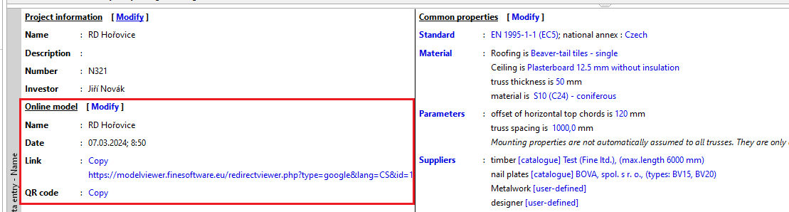 Properties of online model on the main screen
In the "Online model" window it is possible to edit the name of the project and then upload the model to the web (button "Create"). For the following work it is possible to use the buttons "Update" (updates the model while keeping the link) and "Remove". The window also displays the URL of the model, both as a link and as a QR code. If an online model exists for the project, the QR code with the link is automatically displayed in the bottom left corner of the drawing.
The new engineering manual "Online model" is dedicated to this feature.
Default settings for walls
The "Truss 3D" program now provides an option to enter the default wall properties (thickness, height, wall plate, roof plane pitch, etc.). This option is available in the default settings "Project settings", where there is a new section "Templates". When creating a new project, these properties are taken over into the initial wizard and then also into the wall template.
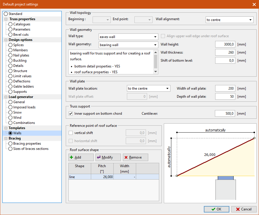 Default settings for walls
Option to set the default eccentricity of web in support
In the "Project/truss settings" it is possible to modify the default web eccentricity in the supported joints on the bottom chords, where one web goes. Previously, the eccentricity was automatically set so that the axis of the web intersected the axis of the bottom chord at the joint. This method of positioning the web does not create additional bending moments which can negatively affect the bearing capacity of the bottom chord. Using the new setting, the default position of the web can be adjusted.
The default position of the web is set by the dimensional-free coefficient "Web eccentricity in support", which can take values in the range <0; 1.0>. The factor represents the eccentricity of the web connection expressed as a proportion of the bottom chord depth. The eccentricity is measured from the bottom edge of the bottom chord. Thus, a value of 0 means that the web axis intersects the bottom edge of the chord at the joint. A value of 0.5 corresponds to the current behavior of the program, i.e. that the web and chord axes intersect at the joint. If a value of 1.0 is specified, the web axis intersects the upper edge of the chord directly above the joint.
The setting affects the default behavior of the webs in all supported joints on the bottom chord with one web. If it is necessary to select a different solution in each joint, the eccentricity must be adjusted in another way, for example in the member properties.
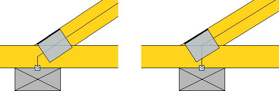 Details with the default eccentricity 0.5 and with the eccentricity 1.0
Optimization of the nail plate design
The design of the nail plates has been optimized and should result in a more economical design in some cases.
Factor of uncovered joint line
The determination of the nail plate length for tension, compression and shear analyses is in accordance with Section H.5(1) of the new generation of Eurocode 5. According to this standard, only the joint line that is covered by the timber, extended by 12t (i.e. the plate thickness) into the uncovered part of the plate, can be considered. This provision is not included in the current version of Eurocode 5. Using the "Factor of uncovered joint line" in the "Nail plates" section of the "Project/truss settings", the length of the extension taken into account can be adjusted.
Graphical diagrams of internal forces
In the "Detailed documentation" part of the structural documentation, a new way of listing the internal forces has been added in the form of graphical diagrams on the structure. These diagrams can be printed for load cases and combinations. The range of diagrams can be limited by setting "Selected members/load cases/combinations".
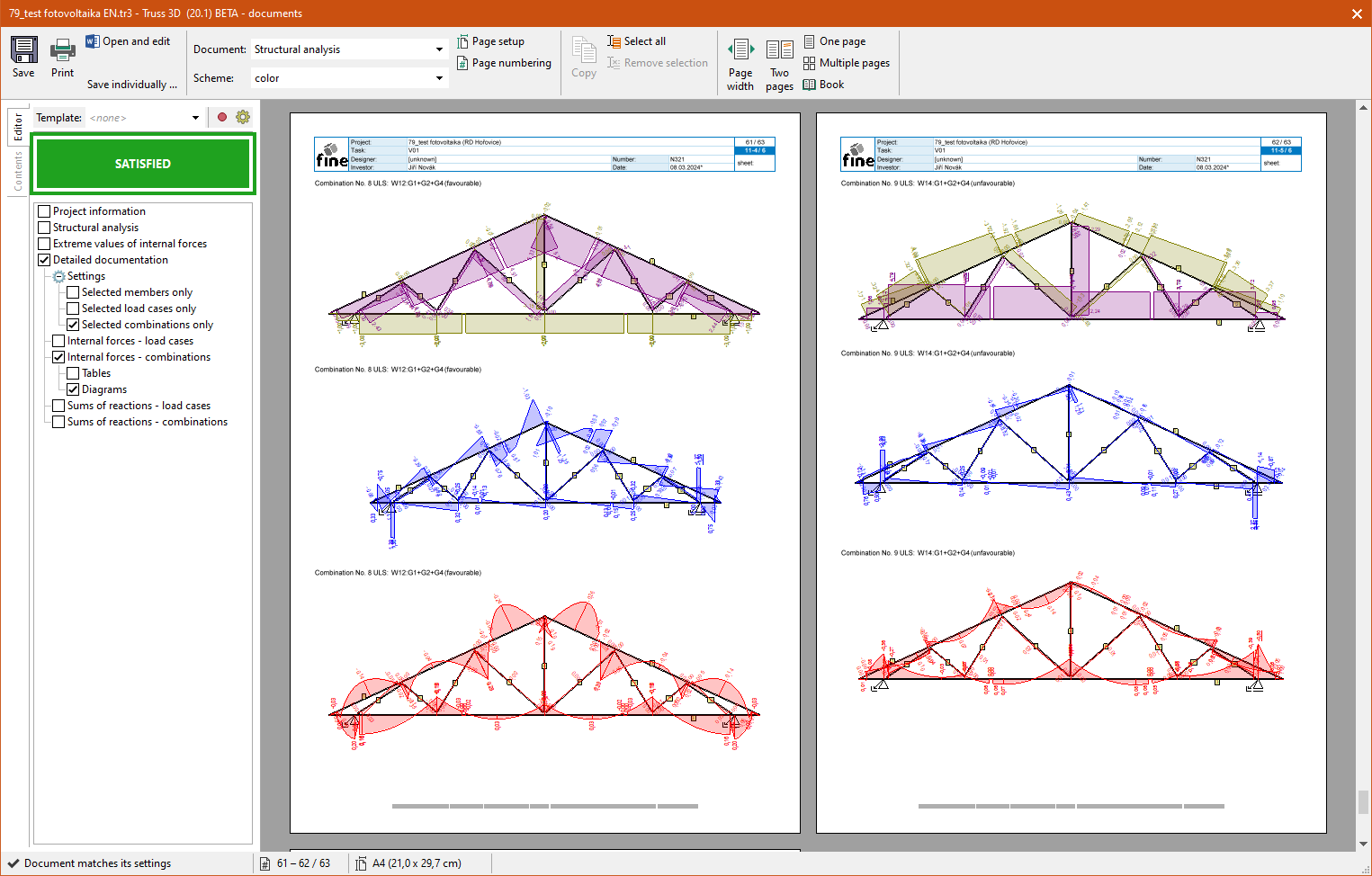 Diagrams of internal forces
Total lengths of members in manufacturing documentation
The "Summary" table in the "Members" section of the manufacturing documentation now also contains information on the total length of members.
File *.mxf for saw machines
The range of export files for saws has been extended by the *.mxf format.
Saving data on cloud storage
All programs include a new window for opening and saving files. This window allows direct writing and reading from selected cloud storage devices that can be used to share data within the company. The original appearance of the windows can be reverted using the "Use Windows Dialog" button at the bottom of the window. Currently, Google Drive, OneDrive, Amazon S3, Amazon S3 compatible storage (e.g. S3 server on Synology NAS) are supported. The list of supported storage will gradually expand.