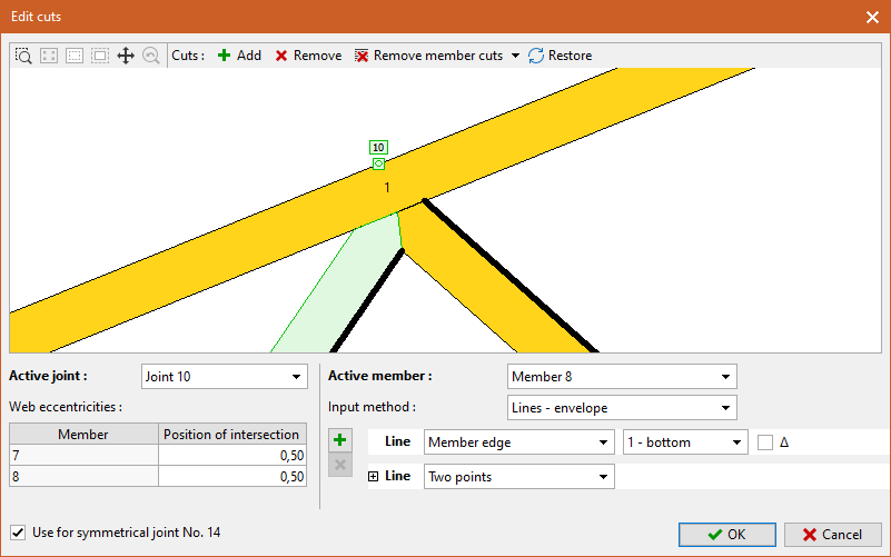
Edit cuts
This window is used to modify the geometry of the joints. It is mainly for arbitrary input of end cuts, but it is also possible to change the eccentricity of the connected webs. The window contains two basic parts: a workspace for graphic work and a frame with the properties of the active joint and the member in the lower part. The workspace allows the display of the construction layer (can be switched on with the "![]() " button) and the construction lines ("
" button) and the construction lines ("![]() " button). Multiple joints can be edited sequentially within a session, the transition between joints can be done either by clicking on the joint mark on the workspace or by using the drop-down list in the "Active joint" section.
" button). Multiple joints can be edited sequentially within a session, the transition between joints can be done either by clicking on the joint mark on the workspace or by using the drop-down list in the "Active joint" section.
Editing of cuts
The workspace and the "Active member" frame at the bottom of the window are used for editing cuts in the active joint. Normally, the cuts are created automatically by the program, so by default each joint has the "Create cuts automatically" setting checked in the bottom left corner of the window and most of the options in the "Active member" section are not accessible. When any operation is performed on the workspace, this setting is automatically disabled and the joint goes into manual cut entry mode. In this mode, for example, the joint stops responding to the cutting method selected in the "Joint Properties". Checking this setting again will cause the loss of user entered cuts and the joint will return to automatic mode.
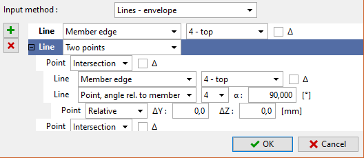
When editing cuts, you must first select the "Input method" at the bottom of the window. The following options are available:
- Lines - envelope - the most common method of input, individual cuts are entered in any order, the resulting shape of the cut part is the envelope of all entered cuts. Only convex shapes can be entered in this way.
- Lines - order - this method of input is similar to "lines - envelope", but the individual cuts are entered in a fixed order starting from the point highlighted by the blue circle on the workspace. The resulting shape of the member end is a polygon whose segments are the entered cuts in the given order. Concave shapes can also be entered in this way.
- Polygon - in this method of input, it is not the cuts that are entered, but the points of the polygon that will form the member end. The points must be entered in the correct order starting from the edge whose end is highlighted by the blue circle. Concave shapes can also be entered in this way.
The easiest way to modify the geometry of cuts is graphically on the workspace. First, it is necessary to click to select the active joint and member (they are highlighted in green). It is not possible to select a continuous member as the active member since it has no cut in the joint. The following tools are available for work in the toolbar at the top of the workspace:
- Add - a mode in which new cuts can be entered on the active member. When this mode is selected, new cuts can be entered either by clicking on any existing edge in the joint or by entering two points that define the cut. Any number of cuts can be entered without interruption. During the entry process, the active member can be changed with a single click and work can continue. The mode can be stopped by right-clicking, pressing the "Add" button again or selecting another mode.
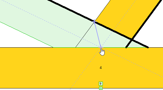 Entering a cut using two points: the intersection of the top edges and the intersection of the web axes
- Remove - This mode is used to remove existing cuts on the active member. The available cuts on the active member are highlighted on the workspace, the removed cut is always underlined in red. This mode works in the same way as "Add", so it allows to remove multiple cuts in a row and to change the active member during the work.
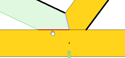 Removing cut
- Remove member cuts - Allows to remove all cuts on the active member with one click. By pressing the "
 " icon, the "Remove joint cuts" tool is also available, which removes all cuts of all members in the joint at once.
 - Restore - this tool will return the default cutting method for all members in the joint. However, it does not override the "Create cuts automatically" setting, so the joint remains in manual mode.
Cuts can also be entered and modified parametrically in the lower part of the window. This method is less clear, but it allows to enter more complex types of cuts (perpendicular to the member, offset from the edges, etc.). The following buttons are available for parametric entry of cuts:
- Add - inserts a new cut or point (in the case of the "Polygon" input method). The cut or point is inserted into the list after the active item in the list (highlighted in blue).
- Delete - Deletes the selected (highlighted in blue) cut or point
- Move Up - Moves the cut or point up one place in the list. The button is not available for the "Lines - envelope" mode, where the order of the items does not matter
- Move down - moves the cut or point in the list one place lower. Button is not available for " Lines - Envelope" mode, where the order of items does not matter
The range of inputs is then adjusted according to the type of cut or point. In addition to unambiguous inputs such as edge selection, the following markers are used:
- Δ - distance (offset) of the cut from the selected line
- ΔY - distance from the selected point in the horizontal direction
- ΔZ - distance from the selected point in the vertical direction
- α - angle of deviation, positive direction is measured counterclockwise
For clarity, the properties of cuts or points are hidden in the default view, they can be shown by the "+" mark in front of the item.
 Cut properties
Both input methods can be combined freely. It is therefore possible to enter the cuts graphically and then add some parameters to them in the lower part of the window, such as the offset.
Adjusting web eccentricities
In the "Active joint" section in the lower left corner of the window, you can change the eccentricity of the webs connected to the joint. By default, the webs are designed so that the intersection of the end cuts lies in the web axis. The user can change the position of the intersection in this part. This may be to reduce the bending moment induced by the eccentric connection of the web or to extend the length of the joint for the nail plate design. The position of the intersection is given as a proportion of the section depth. The permissible range of values is <0;1,0>. The value 0,5 represents the position of the intersection at half the section depth, i.e. in the axis of the member. When the value 0 is entered, the member is aligned to the center of the intersection by the edge highlighted in bold. This results in only one cut on the web. If the value 1.0 is entered, the web is aligned to the centre of the joint with the second (unhighlighted) edge.
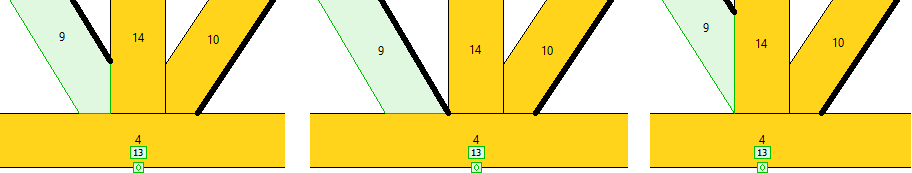 Different eccentricity values for the web 9: 0.5 (default value), 0 and 1.0
Multiple joints can be edited sequentially in the window. After confirmation with the "OK" button, the modifications are transferred to the truss. If the setting "Use for symmetrical joint" is checked in the lower left corner, the cuts in the corresponding symmetrical joint are also adjusted.
 Window "Edit cuts"