Version 16
New features in the version 16:
Drawing tools in the programs "Truss 2D" and "Truss 3D"
The programs "Truss 2D" and "Truss 3D" contains a new toolbar which contains basic drawing tools. This part substitutes construction lines which were included in previous versions.
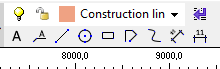 Toolbar "Drawing"
The upper part of the toolbar contains drop-down menu with list of drawing layers. This list and can be modified with the help of the button which is placed on the right side of the drop-down menu. The button launches the window "Layers" where can be modified also properties of layers (name, colour, on/off, line type, thickness etc.).
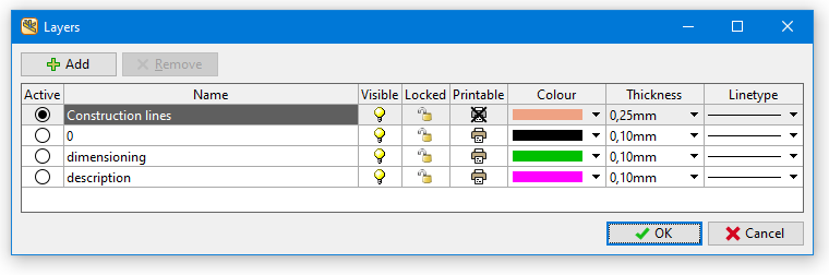 Windows "Layers"
The bottom part of the toolbar contains following functions:
| Text |
|
| Text with line |
|
| Line |
|
| Circle |
|
| Rectangle |
|
| Polyline |
|
| Spline |
|
| Dimension aligned |
|
| Dimension linear |
|
The object properties can be modified in the frame which can be expanded on the right side of the workspace.
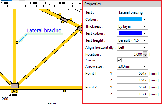 A frame with object properties
Objects included in the printable layers are automatically displayed in the output documentation.
CAD tools for topology edit in Truss 2D
The program "Truss 2D" contains new CAD-like functions for graphical editing of objects on the workspace. They are located in the new toolbar "Edit". These tools can be used for manipulation with truss parts (joints, members) as well as with objects created using drawing tools (text fields, lines etc.). Functions in this toolbar also replace tools placed in the former toolbar "Construction lines". List of functions in the toolbar:
| Remove |
|
| Multiple copy |
|
| Move |
|
| Stretch |
|
| Mirror |
|
| Rotate |
|
| Equidistant |
|
| Extend |
|
| Extend/Trim |
|
Editable web eccentricities
The new mode of cutting webs in joints was added in the "Project/truss settings" part "Structure". The mode is called "Editable position of webs in joints" and brings an option to modify eccentricities of individual webs in the "Detail properties" tab "Others". These eccentricities may significantly affect bending moments in joints or length of joint line during the plate verification.
The web eccentricity is defined as a position of end cuts intersection defined relatively to the cross-section depth. Permissible values are <0;1.0>. The value 0.5 means that the intersection of cuts is in the member axis. The value 0 means that the intersection lies on the highlighted edge (red bold line) of the member. Web will have only one cut at the end in this case. The opposite value 1.0 means that the second member edge is aligned into the joint center.
The tab contains also non-active scheme which shows web orientation. This scheme does not reflect changes of inputs. Closing the window and mounting is essential for checking real geometry.
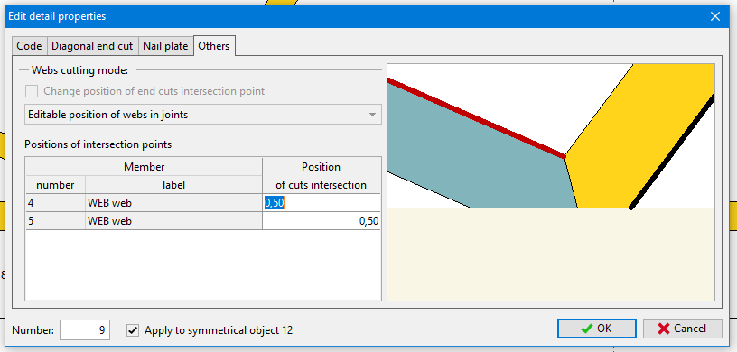 Editable eccentricities in "Detail properties"
Improvements in the design according to DIN EN 1995-1-1
The automatic design according to the German annex DIN EN 1995-1-1 was improved. The changes include modified rule for overlap of plate on member, excluded in-plane buckling in joints etc. The documentation of structural analysis was also modified according to the needs of German market.
Export of *.dxf for SL laser
All programs can produce *.dxf files optimized for laser projection produced by SL Laser company. Since *.dxf is a general drawing file, these files can be used also by laser projections supplied by other manufacturers.
Option to change the number of first timber member in the cutting list
The beginning of numbering can be specified for batched documentation produced by programs "Truss 3D" and "Truss Explorer". This option is included in the tab "Documentation" of "Application options". This feature may reduce collisions in production when more projects are produced parallelly.
Option to start a new roof macro as a copy of an existing one
New macro in the part "Roof" can be now created as a copy of existing macro. This option is included in the drop-down menu which appears after clicking on the button "Add new macro".
Customizable colour scheme of documentation
The window "Page properties" contains the new part "Appearance" with menus for changing the heading and background colours.
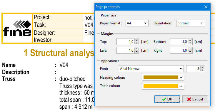 Appearance settings for documents
Improvements in the documentation of structural analysis
The documentation of structural analysis was modified partially. The list of combinations was simplified and there is a new option to print details of structural model. Documentation of structural analysis can use different font size comparing to other documents, since parameters specified in the window "Page properties" are stored separately for this document.