This frame contains the option of selecting the standard and related analysis parameters. There are two standards to choose from: "EN 1995-1-1" (Eurocode 5) a "SANS 10163-1" (South Africa).
National annex | - In this option, the national annex that will be used for the design and verification of the structure can be selected. In addition to the national annexes of each country, the options "EN 1995-1-1" (basic version of the design standard without any national annex) and "user-defined" (allows you to enter your own values for the design parameters in the "Design Customizing" window) are also available.
|
Verification method for compression in supports | - Option to choose how the compression perpendicular to grain in supports will be verified. The default option "according to national annex" use the rules given for the selected national annex. If the option "EN 1995-1-1" is selected, the design shall be carried out according to the basic version of this standard. The options "SS EN 1995-1-1" and "NS EN 1995-1-1" offer a verification in accordance with the Swedish and Norwegian National Annexes. These national annexes contain alternative procedures which are compatible with EC5. The verification is described in detail in the chapter "Compression perpendicular to the grain in supports" of the theoretical part of the help.
|
Service class | - Choice of service class where the structure will be situated. The definition of the service class is given in chapter 2.3.1.3 of the standard and depends on the ambient temperature and ambient humidity. "Service class 1" corresponds approximately to a heated indoor environment, "Service class 2" to an unheated indoor environment and "Service class 3" to other variants (e.g. structures partially exposed to the weather). In "service class 3", the suitability of using nail plate trusses should be considered or appropriate measures should be taken (e.g. use of stainless steel nail plates). The service class affects the determination of the strength characteristics of the timber and also the calculation of the deflection.
|
Use own value of ksys | - If this check box is ticked, the value of the ksys factor can be entered to take into account the system strength (load distribution between trusses). The factor can take a maximum value of 1.1 in accordance with paragraph 6.6(2). For timber trusses, this factor can be used if the axial distance does not exceed 1.2 m, the transverse elements (battens, purlins, panels) are continuous over at least two bays and their joints are staggered.
|
Use own value of γm2 | - If this box is checked, the value of the γm2 factor can be entered to take into account the load sharing. The coefficient may take the value 0.87 in accordance with paragraph 13.1.2.2. The factor can be used if the trusses have similar deformations and if the loads are are spaced not more than 600 mm apart.
|
Moisture content | - Option to specify the timber moisture content. The available options are based on the rules for deflection calculation (d2 factor according to chapter 12.2), but the choice also affects the wood design (γm4 factor according to paragraph 13.1.2.4).
|
Factor γm4 | - In cases where the "Moisture content" option does not allow the exact classification of the structure with regard to the determination of the γm4 factor value, this classification can be done manually by this setting. If the moisture content of the pressed elements can exceed 200 g/kg, a value of γm4 equal to 1.3 is considered (paragraph 13.1.2.4).
|
Factor γm5 | - This setting takes into account the negative impact of some pressure treatments and fire retardants on the timber strength characteristics using the γm5 coefficient. If the check box is ticked, this coefficient takes the value 1.11 in accordance with Article 13.1.2.5.
|
Position of chords in the structural model | - This setting allows you to select the position of top and bottom chords in the structural model. The position is entered as a number in the range <0;1,0>. This number corresponds to the ratio of the distance of the system line from the outer edge of the member to the member depth. If a value of 0 is specified, the outer members are modelled at the outer edges (top edge for rafters and bottom edge for bottom chords). If a value of 1.0 is entered, the outer members are modelled at the inner edges. If the outer members are modelled in the axis of the timber, this number takes the value 0.5.
|
Bracing style | - This setting selects how the structure will be braced. The option affects the calculation of the out-of-plane buckling on the top chords. The following options are available: "Type A - bracing using loose timber" represents the bracing of the top chords with diagonal timber braces on the underside of the chords, "Type B - bracing frames" corresponds to the use of bracing trusses in the roof plane, and "Type C - gable trusses connected to the wall" is used in cases where the gable truss is continuously connected to the gable wall. If option "A" or "not specified" is selected, the maximum of the batten distance and the centreline distance of the trusses shall be considered as the buckling length of the top chords for the out-of-plane buckling calculation. If option "B" or "C" is selected, the out-of-plane buckling length shall always be the battening distance.
|
Compressive forces in joints | - The option to set how the distribution of compressive forces in the connections will be handled. There are several options for the force splitting between the nail plates and the contact of the timber elements. The most effective option is the "split compressive force automatically" option, which assigns the maximum compressive force to the contact between the timber elements and the rest is used for the design of the nail plate.
|
Structural model | - In this option, it is possible to select a structural model which will be used for calculation of internal forces.. There are two options to choose from: the "NF DTU 31.3" option creates the structural model according to the French standard NF DTU 31.3 part 3. In the "DIN EN 1995-1-1" option, the structural model is created according to the German national annex and related documents.
|
Connections (ULS) | - This option allows user to set the connection style when calculating the internal forces for the ultimate limit state. When selecting the connection type, the standard provisions (e.g. EN 1995-1-1, section 5.4.2) should be respected. Some national annexes to EN 1995-1-1 provide detailed rules, so the range of options may be limited.
|
Connections (SLS) | - This option allows you to set the way the connections are modelled when calculating deformations for the serviceability limit state. The only option that takes into account the slip of the connections directly in the calculation is "spring connection".
|
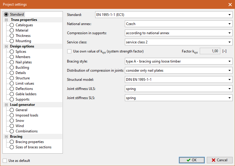 Tab "Standard"