Version 19
New features in the version 19:
Discontinuation of support for the original mounting and some design standards
As part of the program optimization, support for the original method of modeling trusses based primarily on joint and member codes has been discontinued. From version 19 onwards, it is also no longer possible to use the expired standards CSN 73 1701 and STN 73 1701 in the design process.
Version 19 supports only the new modelling method, in version 18 marked as "General Geometry".
Only the design standards EN 1995-1-1 (Eurocode 5) and SANS 10163-1 remain available for structural design. The range of available national annexes to Eurocode has not changed. If older structures need to be recalculated using CSN/STN 73 1701, version 18 must be used.
Bulk editing in Truss 3D
Bulk editing of joints, members and connections that were previously only available in "Truss 2D" has been added to the "Results" section of Truss 3D. When viewing individual trusses, it is thus possible to easily edit the properties of selected entities. The code, support and position can be changed for the joints, the code, profile and material for the members and the type and size of the nail plate for the connections. Bulk edits are made in the "Properties" sidebar, which appears to the right of the 2D workspace.
Bulk editing is particularly useful when adjusting section depths, entering supports in bulk, or unifying the dimensions of plates in a truss.
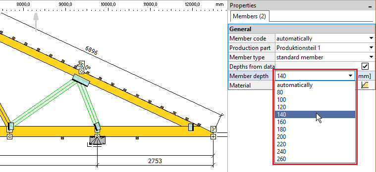 Editing timber depth for selected webs
Bulk editing of points and walls
The "Truss 3D" program now also allows bulk editing of selected points and walls. For points, it is possible to enter the properties of the structure (column, chimney), and for walls, all the data from the "Geometry" tab (wall type, dimensions, wall plate, etc.). Similarly to the trusses, editing is done in the "Properties" sidebar, which is located to the right of the 2D workspace.
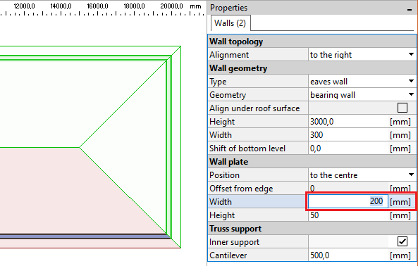 Editing wall plate in selected walls
Copy between trusses or projects
The option to copy selected elements ( members, joints, nail plates) between individual trusses has been added to the program. The copying can be done freely both within one 3D project and between different projects created in "Truss 2D" or "Truss 3D". Before copying, it is necessary to select the corresponding elements and then use the "Copy selected" tool. This tool is located in the context menu, which is available by right-clicking. Alternatively, the keyboard shortcut Ctrl+C can be used.
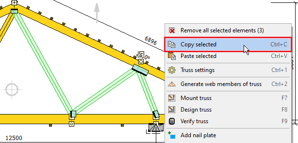 Tool "Copy selected"
After selecting the tool, it is necessary to specify the selection reference point. The selected elements can then be inserted into either the same or a completely different project using the "Paste selected" function. The keyboard shortcut Ctrl+V can also be used. When inserting, the insert point must be selected.
This tool can be used, for example, when copying a webbing, more complex detail or nail plates from one truss to another.
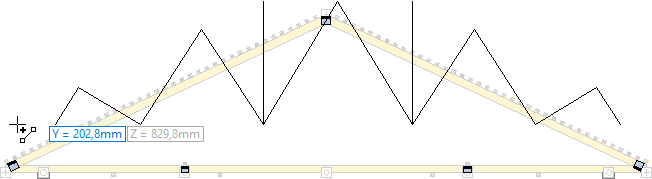 Inserting webbing from another truss
Graphical editing of cuts in joint
A new window "Edit cuts" for graphical editing of end cuts has been created, replacing the existing tool "Cut member with general line". It can be found in the context menu of the workspace or member as "Edit cuts". In "Truss 2D" it is also accessible via the "![]() " button in the "Tools" toolbar.
" button in the "Tools" toolbar.
The window contains two basic parts: a workspace for graphic work and a frame with the properties of the active joint and the member in the lower part. The workspace allows the display of the construction layer (can be switched on with the "![]() " button) and the construction lines ("
" button) and the construction lines ("![]() " button). Multiple joints can be edited sequentially within a session, the transition between joints can be done either by clicking on the joint mark on the workspace or by using the drop-down list in the "Active joint" section.
" button). Multiple joints can be edited sequentially within a session, the transition between joints can be done either by clicking on the joint mark on the workspace or by using the drop-down list in the "Active joint" section.
The following tools are available for work in the toolbar at the top of the workspace:
- Add - a mode in which new cuts can be entered on the active member. When this mode is selected, new cuts can be entered either by clicking on any existing edge in the joint or by entering two points that define the cut. Any number of cuts can be entered without interruption. During the entry process, the active member can be changed with a single click and work can continue. The mode can be stopped by right-clicking, pressing the "Add" button again or selecting another mode.
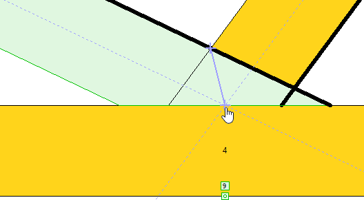 Entering a cut using two points: the intersection of the top edges and the intersection of the web axes
- Remove - This mode is used to remove existing cuts on the active member. The available cuts on the active member are highlighted on the workspace, the removed cut is always underlined in red. This mode works in the same way as "Add", so it allows to remove multiple cuts in a row and to change the active member during the work.
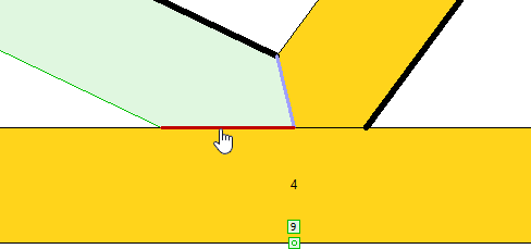 Removing cut
- Remove member cuts - Allows to remove all cuts on the active member with one click. By pressing the "
 " icon, the "Remove joint cuts" tool is also available, which removes all cuts of all members in the joint at once.
 - Restore - this tool will return the default cutting method for all members in the joint. However, it does not override the "Create cuts automatically" setting, so the joint remains in manual mode.
Any use of the graphic tools cancels the "Create cuts automatically" setting in the lower left corner of the window for the active joint, and the joint switches to manual cut input mode. When this setting is checked again, all manual editing disappears and the program solves the cuts automatically again. The lower part of the window also contains the possibility to change the eccentricities of the connected webs and other properties of the cuts, which were previously located in the "Joint properties".
A detailed chapter is available in the program help for the "Edit cuts" window. If the window is active, this chapter can be called up with the "F1" key.
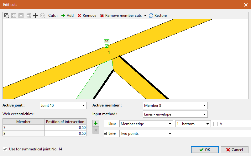 Window "Edit cuts"
Tool for rounding point coordinates
A tool for rounding absolute point coordinates has been added to "Truss 3D" program. This tool can be used in cases where the geometry of the structure was created by importing inaccurate drawing and where the parallelism of walls is compromised. In these cases, the point coordinates should be rounded to the appropriate level. The function "Round coordinates of points" is applied to the selected points. If the coordinates of all points need to be rounded, the entire structure can be selected (e.g. with the keyboard shortcut Ctrl+A). The tool is available in the context menus of the workspace and point table if at least one point of the structure is selected.
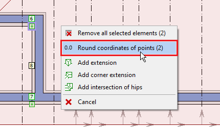 Coordinate rounding tool in the workspace context menu
After selecting the tool in the context menu, a dialog box appears where the coordinates to be rounded and the rounding accuracy can be selected. The default precision of "0" represents rounding to whole millimeters. A value of "10" will round the coordinates to tens of millimeters, i.e. centimeters.
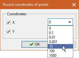 Selecting the rounding precision
Enhanced drawing functions
The new version also brings minor improvements to the graphic functions:
- Multiple copying for equidistant - when using the "Equidistant" tool, the number of repetitions can now be specified. The input is done after entering the distance of the equidistant and can be done directly from the keyboard. The entered value is displayed at the cursor.
 Multiple copying for equidistant
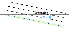
- Extend by crossing out - the "Extend/Trim" tool allows selection by crossing out. When selecting elements to extend or trim, if a point is clicked outside of the element on the workspace, the program will allow a second point to be entered. The program will then trim or extend all the elements that have been crossed out by the line connecting the two specified points.
- Selection by crossing out - if the "Alt" key is pressed during selection, the program does not select by default with a rectangular box, but by crossing out
Dark display mode
All programs can be set to dark display mode. The "Color Mode" option is available in the "Display" section of the main menu. In addition to the light, dark and grey modes, there is also an automatic selection according to the operating system settings. After changing the color mode, it is necessary to restart the program.
 Dark display mode
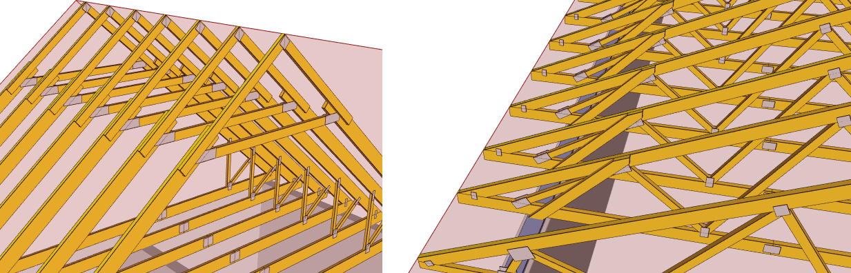
Bevels in gable ladders
Bevels are now automatically created on the gable ladder, provided they are enabled for the whole structure. Bevels are created in both the top and the eaves.
 Gable ladder with bevels
New type of bevels for multi-ply trusses
The bevels on multiple trusses has been modified if the "All plies identical in multi-ply girders" option is selected. Now, bevels respect also the setting "symmetrical detail for single cut". If this setting is used, all layers have the same double-cut bevel.
|
|
Identical plies with single cuts | Identical plies with double cuts |
Alignment of production parts
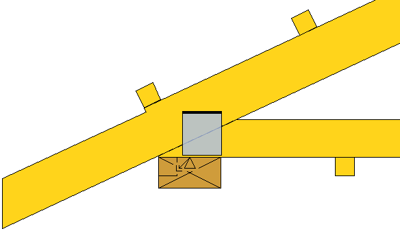
For production parts, it is now possible to specify the mutual alignment. In addition to the display in Truss 3D, this setting is also used in the design of nail plates. The program does not check the overlap of members with the nail plate if they are in a production part with a different alignment than the production part of the plate. The alignment is selected in the "Truss 2D" program in the "Production parts" table.
When using production parts with a different alignment, keep in mind that this connection causes additional out-of-plane stresses on the truss that are not considered in the calculation. Therefore, these connections should only be used when connecting substructures to the main supporting truss.
 Examples of aligned production parts
Extended options for structural model
A new type of end conditions of parts in the structural model (now labeled "Joint stiffness ULS/SLS") called "fixed with spring rotation" has been added to the program. In this new method, the two displacements in the member end are modeled as rigid (similar to a fixed or hinged connection), and the rotation is modeled according to the real plate stiffness (as in a spring connection). In general, this method is between a fixed and a hinged connection. In contrast to the pinned connection, no significant additional moments caused by hinge eccentricity appear in joints. Compared to the fixed connection, the nail plates plates are subjected to more realistic bending moments. This option (similarly to pinned or fixed ends) may be restricted or prohibited in some national annexes (e.g. Germany, France).
The end conditions can now be chosen differently for the ultimate limit states and for the serviceability limit states. For example, it is possible to set the internal forces for the ultimate limit states to be calculated without the effect of slip in the connections and the deformation for the serviceability limit states to include slip.
The options for the structural model and the end conditions of the members have been moved from the "Structure" tab to the "Standard" tab within the "Project/Truss Options" window.
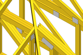
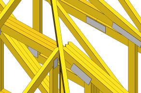
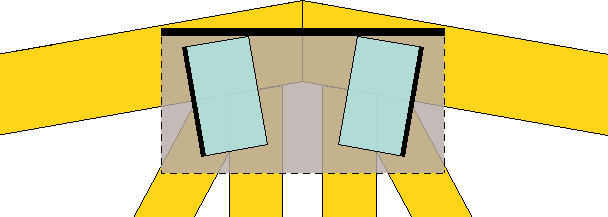
Adjusting the position of the vertical web in the eaves detail
The setting "Modify eccentricity of vertical webs in hip detail" in the tab "Structure" of "Design options" allows to select automatic tilting of the verticals leading to the hip detail if the intersection of the lower edges of the upper chords is outside the original position of the vertical web. In such cases, only one chord would be in contact with vertical web end which complicates the design of the nail plate. Therefore, the program moves the upper end of the vertical web so that the intersection of the lower edges of the chords meets the axis of the vertical web. These situations occur mainly when the dimensions of the rafter and horizontal top chord in the hip detail differ significantly.
 Hip detail without and with modified eccentricity of vertical web
Editable position of outer members in structural model for SANS 10163-1
If the design standard "SANS 10163-1" is selected, it is possible to change the position of the design members of the chords in the structural model. The position is determined by a coefficient which can take values from 0 (outer edge of the member) to 1.0 (inner edge of the member).
Transfer of compressive forces in joints according to DIBt
A new method of transferring compressive forces in joints "Analysis according to DIBt" has been added. It can be found in the "Design options" window, "Standard" tab. If this option is selected, the program does not consider transfer of compressive forces by contact between the timber members if at least one of the components in the joint is subjected to compression perpendicular to the grain. At the same time, the anchorage capacity of the nail plates is reduced by a factor of 1.1.
This setting is recommended for use in Germany in combination with nail plates which have the above rules prescribed in the relevant certificate "Allgemeine Bauartgenehmigung" issued by the Deutsches Institut für Bautechnik (DIBt).
Graphical view of the results of the nail plate verification
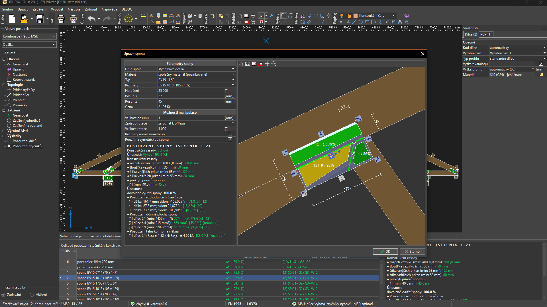
The detailed results of the plate verification are now also displayed on the workspace by highlighting the connection areas and joint lines in colour. A colour scale from dark green to orange is used for drawing up to 100% load capacity, and a scale from light red to dark red is used for load capacity above 100%. When drawing joint line utilization, the worst utilization for each segment is always shown in case of overlapping results.
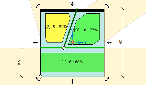 Graphical representation of the plate results
Enhancement of the tool "Align according to the symmetry axis"
The "Align according to the symmetry axis" function (button "![]() ") in the "Truss 2D" toolbar can now be used for symmetrical alignment of nail plates and general connections.
") in the "Truss 2D" toolbar can now be used for symmetrical alignment of nail plates and general connections.
Option to specify custom nail plate size
It is possible to enter custom dimensions of the contactor plate in the "Edit nail plate" window. If the "Custom nail plate size" item is selected in the "Dimensions" item, the table displays an input field for entering the width and length of the contact plate.
The drop-down list of nail plate dimensions can be long and navigating it may not be easy. Due to the fact that keyboard input always works in the active drop-down list, keyboard input of "c" (i.e., the initial letter of the "Custom nail plate size" text) may be a faster alternative to long scrolling to the top of the list. Of course, the drop-down list must be active, i.e. underlined in blue. The list is then automatically set to this entry and the fields for entering the width and length are made available.
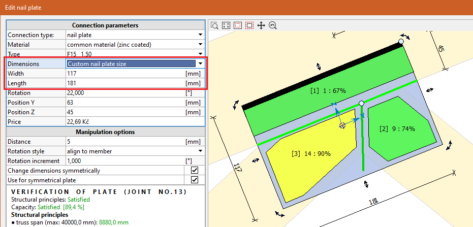 Specifying custom dimensions of the nail plate
Display of results for wall plates in Truss 3D
The "Truss 3D" program now displays the result for wall plates on the workspace in the mode "Joints results". The result is represented by the colour of the wall plate, using the same colour scale as for the nail plates. The exact utilization value is displayed below the wall plate.
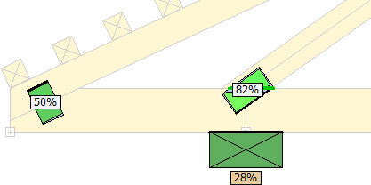 Wall plate with displayed result of analysis
Optimization of the "Project/truss options"
The "Project/Truss Options" windows have been simplified. Settings that are not used in the general geometry have been removed. The number of tabs has also been reduced. The main changes are:
- Standard - now includes options for structural model and connection stiffness (moved from "Structure" section).
- Parameters - now also contains data from the "Material" and "Thickness" sections
- Bevels - the original "Mounting" section has been renamed as it no longer contains other data
- Deflections - it is possible to quickly set moderate or strict deflection limits according to the standard. The appropriate type of limit can be selected in the frame header and confirmed with the "Set" button.
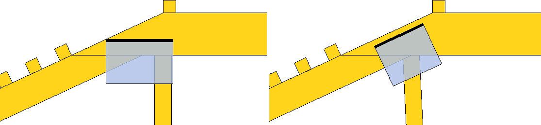
Upper notch in the eaves detail
The upper notch on rafter can now be specified in the bottom and upper detail. It simplifies the realization of soffit on overhangs. The notch can be specified in the properties of the corresponding detail using the length and depth of the notch.
The weakened rafter cross-section is not considered during the design, therefore it is recommended to use this detail only for members with sufficient reserve in bearing capacity.
 Upper notch on rafter
Easier access to exports to CAD applications
The keyboard shortcut Ctrl+E can now be used to call up the CAD export window (in the main menu "File" - "Export" - "Structure" - "CAD formats"). The window also remembers the last used file type, so it is not necessary to re-select the export format every time the window is opened.
Wind load update for SANS 10163-1 (South Africa)
The wind loads for South Africa have been modified to the current versions of SANS 10160-1:2019 and SANS 10160-3:2018. The changes include a new wind area map, modification of the partial factors and a change in the calculation of the basic wind speed.
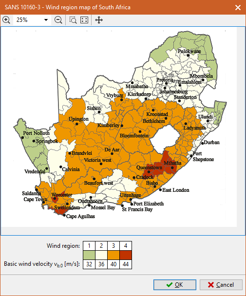 New map of wind zones for South Africa
Changes in the document " Structural Analysis"
The following modifications have been made to the " Structural Analysis" document:
- "Load parameters" - loads that were previously missing (permanent and live loads in the attic, etc.) have been added to the list.
- "Brief list" in the "Load combinations" part - new list of combinations, which significantly saves space. The brief list only contains the nature of the combination, i.e. the presence of permanent or variable loads and the main combination factors. However, it cannot be used for exact determination of particular load cases that are included in the combination. A short list can save up to 80% of the space compared to a full list.
- "Member check" - this section has been divided into the following parts: "Basic verification" (table with the fundamental results for every member), "Slenderness, compression in joints" (results of the slenderness and compression in end joints of the member), "Results for bays" (more detailed assessment by individual bays), "Local deflections" (assessment of the serviceability limit state for each member).
- "Nail plate check" - new option to choose between brief and detailed results
- "Scheme of supports" - before the "Reactions" node, a scheme of the truss with numbering of the supports can now be displayed
- "Forces in general connections" - possibility to list the values of forces in general connections, details are given in the following chapter
Brief list of combinations in documents
In the "Structural analysis" document, it is possible to switch on a brief description of combinations, which saves space in document considerably. The brief description contains only the basic characteristics of the combination, i.e. the presence of permanent or variable loads and the basic combination factors. However, it cannot be used to determine the specific labels of load cases that are included in the combination. A short list can save up to 80% of the space compared to a full description. This method of listing combinations can be enabled in the tree menu of the printing window using the "Brief description" node in the "Combinations" section.
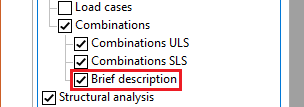 Brief description for combinations
Listing of internal forces in general connections
In the "Structural analysis" document, you can now find a listing of the internal forces in the general connections. This output replaces the "Forces in truss cuttings" that were available for divided structures created using original modelling core. Two options are available: a simpler "For production parts" and a more detailed "For members" listing. The maximum and minimum normal force (i.e. maximum tension and compression), maximum shear force and maximum bending moment are always listed for each production part. For each of these values, the combination number and other corresponding internal forces in the combination are also listed. The maximum values are highlighted in bold. If more than one extreme value occurs in one combination, the combination is listed only once, but more values are highlighted in bold.
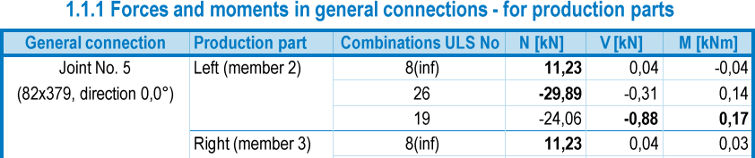 Internal forces in general connection
The table "For production parts" contains a list of internal forces for each production part in the connection. It is the resultant of all members of the given production part, which is referred to the center of gravity of the structural connection and oriented to the coordinate system of the connection. The normal force thus represents the force component in the main direction of the joint (highlighted by the thick edge on the workspace), i.e. in the direction of the "length" dimension. The values in this list therefore represent the forces applied to the structural element of the connection ( timber scab, steel plate, etc.). This table can be used for the design of the structural element of the connection and the fasteners when designing common types of structural connections with two production parts where the forces are transmitted primarily from one significantly loaded member. A typical example is a structural connection on a tensioned bottom chord that does not interfere with other members or interferes with them only marginally. Where a structural connection overlaps multiple heavily loaded components from a single production part (for example, the top chord and the web in the apex joint), the data in this table can be used to design the structural element of the connection. However, the table does not contain sufficient data for the design of fasteners for individual members within a production part.
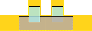 Simple general connection for which the table "For production parts" is sufficient
The table "For production parts" is a more detailed table where the maximum internal forces for each member in the joint can be found. This output is particularly useful in cases where a general connection joins several members in one production part and it is necessary to design the fasteners separately for these individual members. The forces are related to the center of gravity of the connection area on the member and are oriented in the direction of the member. In addition to the basic internal forces, the resultant forces (denoted by "N+V3") and the angle between the force and the direction of grain "α" are also listed. The angle between the force and the direction of grain follows the convention for loaded and unloaded edges in Figure 8.7 of EN 1995-1-1.
 A general connection that connects more than one heavily loaded member in a production part
Option to draw the model label in the floor plan
When printing the floor plan, it is now possible to choose whether the model label should be part of the truss description. The model is only shown for trusses that have at least two different models. The model listing is activated with the "Truss label including model" item in the "Properties of the structure dimensioning".
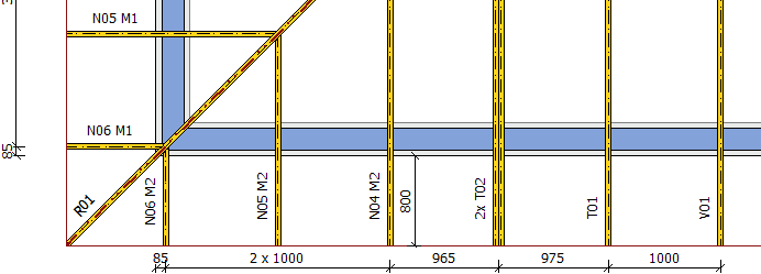 Floor plan with model labels
Warning for inappropriate design location
The "Truss 3D" program now warns before the analysis that a truss is designed without force transfer, even if other trusses are connected to one of its locations. This situation can occur when a truss location without connected trusses is selected as the design location (highlighted in red on the workspace). In this case, the truss may be undersized. The program warns about this fact, the final decision is left to the user. In some cases, this situation may be desired and the lack of force transfer is compensated for by, for example, an increased loading width.
Export file *.bvx for Hundegger saws
The *.bvx format has been added for Hundegger saws, which is now the default format on current Hundegger machines. For this reason, only this format will be further developed. The *.bvn and *.bv formats will still be available, but new features will no longer be added to them.
File *.ccc pro the saw DePauw
New export file *.ccc for DePauw saw was added. This file can be used for DePauw saw with interface based on Windows operating system.
Bevels in the file *.bv for old Hundegger saw machines
The export file for Hundegger P8/P10 saws now includes support for bevels.
Export format for AppliCAD
The structure geometry can now also be exported to *.rxf format for use in AppliCAD.